Functional description
powerSTEP01
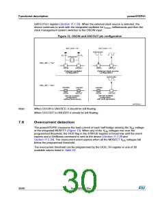
GATECFG1 register (Section 11.1.25). When the external clock source is selected, the
device continues to work with the integrated oscillator for textosc milliseconds and then the
clock management system switches to the OSCIN input.
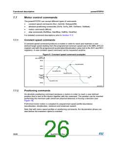
Figure 12. OSCIN and OSCOUT pin configuration
EXT_CLK = "0"
EXT_CLK = "1"
8/16/24/32 MHz
CL
CL
8/16/24/32 MHz
OSC_SEL = "1xx"
OSCIN
OSCOUT
OSCIN
OSCOUT
External oscillator
configuration
External clock source
configuration
2/4/8/16 MHz
OSC_SEL = "0xx"
UNUSED
UNUSED
OSCOUT
UNUSED
OSCIN
OSCIN
OSCOUT
Internal oscillator
Internal oscillator
configuration
configuration
with clock generation
without clock source
AM12830v1
Note:
When OSCIN is UNUSED, it should be left floating.
When OSCOUT is UNUSED it should be left floating.
7.9
Overcurrent detection
The powerSTEP01 measures the load current of each half-bridge sensing the VDS voltage
of the integrated MOSFET (Figure 13). When any of the VDS voltages rise over the
programmed threshold, the OCD flag in the STATUS register is forced low until the event
expires and a GetStatus command is sent to the device (Section 11.1.28 and
Section 11.2.20). The overcurrent event expires when all the MOSFET VDS voltages fall
below the programmed threshold.
The overcurrent threshold can be programmed by the OCD_TH register in one of 32
available values listed in Table 24.
30/90
DocID025022 Rev 1

 STMICROELECTRONICS [ ST ]