powerSTEP01
Functional description
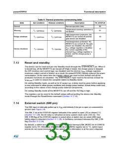
7.8
Internal oscillator and oscillator driver
The control logic clock can be supplied by the internal 16-MHz oscillator, an external
oscillator (crystal or ceramic resonator) or a direct clock signal.
These working modes can be selected by EXT_CLK and OSC_SEL parameters in the
CONFIG register (see Table 40).
At power-up the device starts using the internal oscillator and provides a 2-MHz clock signal
on the OSCOUT pin.
Attention: In any case, before changing clock source configuration, a
hardware reset is mandatory. Switching to different clock
configurations during operation may cause unexpected
behavior.
7.8.1
7.8.2
Internal oscillator
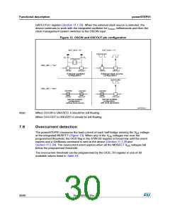
In this mode the internal oscillator is activated and OSCIN is unused. If the OSCOUT clock
source is enabled, the OSCOUT pin provides a 2, 4, 8 or 16-MHz clock signal (according to
OSC_SEL value); otherwise it is unused (see Figure 12).
External clock source
Two types of external clock source can be selected: crystal/ceramic resonator or direct clock
source. Four programmable clock frequencies are available for each external clock source:
8, 16, 24 and 32-MHz.
When an external crystal/resonator is selected, the OSCIN and OSCOUT pins are used to
drive the crystal/resonator (see Figure 12). The crystal/resonator and load capacitors (CL)
must be placed as close as possible to the pins. Refer to Table 7 for the choice of the load
capacitor value according to the external oscillator frequency.
Table 7. CL values according to external oscillator frequency
(2)
Crystal/resonator freq.(1)
CL
8 MHz
16 MHz
24 MHz
32 MHz
25 pF (ESRmax = 80 W)
18 pF (ESRmax = 50 W)
15 pF (ESRmax = 40 W)
10 pF (ESRmax = 40 W)
1. First harmonic resonance frequency.
2. Lower ESR value allows driving greater load capacitors.
If a direct clock source is used, it must be connected to the OSCIN pin and the OSCOUT pin
supplies the inverted OSCIN signal (see Figure 12).
The powerSTEP01 integrates a clock detection system that resets the device in case of the
failure of the external clock source (direct or crystal/resonator). The monitoring of the clock
source is disabled by default, it can be enabled setting high the WD_EN bit in the
DocID025022 Rev 1
29/90

 STMICROELECTRONICS [ ST ]