Highly Integrated Full Featured Hi-Speed USB 2.0 ULPI Transceiver
Datasheet
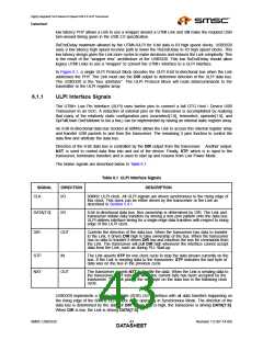
Each time DIR changes, a “turn-around” cycle occurs where neither the Link nor transceiver drive the
data bus for one clock cycle. During the “turn–around“cycle, the state of DATA[7:0] is unknown and
the transceiver will not read the data bus.
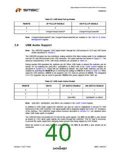
Because USB uses a bit-stuffing encoding, some means of allowing the transceiver to throttle the USB
transmit data is needed. The ULPI signal NXT is used to request the next byte to be placed on the
data bus by the Link layer.
The ULPI interface supports the two basic modes of operation: Synchronous Mode and asynchronous
modes that include Low Power Mode, Serial Modes, and Carkit Mode. In Synchronous Mode, all
signals change synchronously with the 60MHz ULPI clock. In asynchronous modes the clock is off and
the ULPI bus is redefined to bring out the signals required for that particular mode of operations. The
description of synchronous Mode is described in the following sections while the descriptions of the
asynchronous modes are described in Section 6.3, Section 6.4, and Section 6.5.
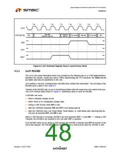
6.1.2
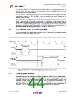
ULPI Interface Timing in Synchronous Mode
The control and data timing relationships are given in Figure 6.2 and Table 4.3. All timing is relative to
the rising clock edge of the 60MHz ULPI Clock.
60MHz ULPI -
CLK
TSC
THC
Control In -
STP
TSD
THD
Data In -
DATA[7:0]
TDC
TDC
Control Out -
DIR, NXT
TDD
Data Out -
DATA[7:0]
Figure 6.2 ULPI Single Data Rate Timing Diagram in Synchronous Mode
6.2
ULPI Register Access
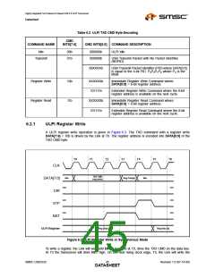
A command from the Link begins a ULPI transfer from the Link to the USB3320. Before reading a
ULPI register, the Link must wait until DIR is low, and then send a Transmit Command Byte (TXD
CMD) byte. The TXD CMD byte informs the USB3320 of the type of data being sent. The TXD CMD
is followed by a data transfer to or from the USB3320. Table 6.2 gives the TXD command byte (TXD
CMD) encoding for the USB3320. The upper two bits of the TX CMD instruct the transceiver as to
what type of packet the Link is transmitting. The ULPI registers retain their contents when the
transceiver is in Low Power Mode, Full Speed/Low Speed Serial Mode, or Carkit Mode.
Revision 1.0 (07-14-09)
SMSC USB3320
DATA4S4HEET

 SMSC [ SMSC CORPORATION ]