Highly Integrated Full Featured Hi-Speed USB 2.0 ULPI Transceiver
Datasheet
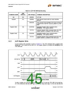
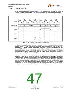
6.2.2
ULPI Register Read
A ULPI register read operation is given in Figure 6.5. The Link drives a TXD CMD byte with DATA[7:6]
= 11h for a register read. DATA[5:0] of the ULPI TXD command bye contain the register address.
T0
T1
T2
T3
T4
T5
T6
CLK
TXD CMD
reg read
Idle
Turn around
Reg Data
Turn around
Idle
DATA[7:0]
DIR
STP
NXT
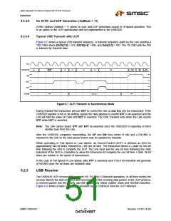
Figure 6.5 ULPI Register Read in Synchronous Mode
At T0, the Link will place the TXD CMD on the data bus. At T2, the transceiver will bring NXT high,
signaling the Link it is ready to accept the data transfer. At T3, the transceiver reads the TXD CMD,
determines it is a register read, and asserts DIR to gain control of the bus. The transceiver will also
de-assert NXT. At T4, the bus ownership has transferred back to the transceiver and the transceiver
drives the requested register onto the data bus. At T5, the Link will read the data bus and the
transceiver will drop DIR low returning control of the bus back to the Link. After the turn around cycle,
the Link must drive a ULPI Idle command at T6.
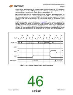
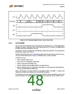
A ULPI extended register read operation is shown in Figure 6.6.To read an extended register, the Link
writes the TX CMD with the address set to 2Fh. At T2, the transceiver will assert NXT, signaling the
Link it is ready to accept the extended address. At T3, the Link places the extended register address
on the bus. At T4, the transceiver reads the extended address, and asserts DIR to gain control of the
bus. The transceiver will also de-assert NXT. At T5, the bus ownership has transferred back to the
transceiver and the transceiver drives the requested register onto the data bus. At T6, the Link will
read the data bus and the transceiver will de-assert DIR returning control of the bus back to the Link.
After the turn around cycle, the Link must drive a ULPI Idle command at T6.
SMSC USB3320
Revision 1.0 (07-14-09)
DATA4S7HEET

 SMSC [ SMSC CORPORATION ]