Highly Integrated Full Featured Hi-Speed USB 2.0 ULPI Transceiver
Datasheet
T0
T1
T2
T3
T4
T5
T6
T7
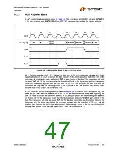
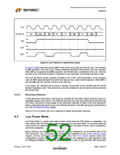
CLK
DATA[7:0]
DIR
TXD CMD
extended reg read
Extended
address
Idle
Turn around
Reg Data
Turn around
Idle
STP
NXT
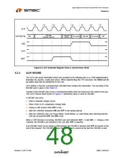
Figure 6.6 ULPI Extended Register Read in Synchronous Mode
6.2.3
ULPI RXCMD
The ULPI Link needs information which was provided by the following pins in a UTMI implementation:
linestate[1:0], rxactive, rxvalid and rxerror. When implementing the OTG functions, the VBUS and ID
pin states must also be transferred to the Link.
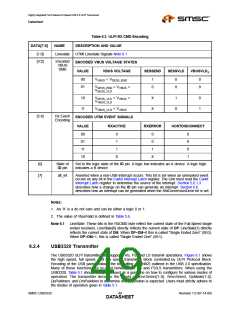
ULPI defines a Receive Command Byte (RXCMD) that contains this information. The Encoding of the
RXCMD byte is given in the Table 6.3.
Transfer of the RXCMD byte occurs in Synchronous Mode when the transceiver has control of the bus.
The ULPI Protocol Block shown in Figure 6.1 determines when to send an RXCMD.
A RXCMD can occur:
When a linestate change occurs.
When VBUS or ID comparators change state.
During a USB receive when NXT is low.
After the USB3320 deasserts DIR and STP is low during start-up
After the USB3320 exits Low Power Mode, Serial Modes, or Carkit Mode after detecting that the
Link has de-asserted STP, and DIR is low.
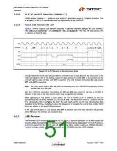
When a USB Receive is occurring, RXCMD’s are sent whenever NXT = 0 and DIR = 1. During a USB
Transmit, the RXCMD’s are returned to the Link after STP is asserted.
If an RXCMD event occurs during a USB transmit, the RXCMD is blocked until STP de-asserts at the
end of the transmit. The RXCMD contains the status that is current at the time the RXCMD is sent.
Revision 1.0 (07-14-09)
SMSC USB3320
DATA4S8HEET

 SMSC [ SMSC CORPORATION ]