Highly Integrated Full Featured Hi-Speed USB 2.0 ULPI Transceiver
Datasheet
Table 5.8 USB Weak Pull-up Enable
RESETB
DP PULLUP ENABLE
DM PULLUP ENABLE
0
1
0
0
ChargerPullupEnableDP
ChargerPullupEnableDM
Note: ChargerPullupEnableDP and ChargerPullupEnableDM are enabled in the USB IO & Power
Management register.
5.9
USB Audio Support
Note: The USB3320 supports “USB Digital Audio” through the USB protocol in ULPI and USB Serial
modes described in Section 6.
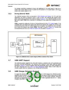
The USB3320 provides two low resistance analog switches that allow analog audio to be multiplexed
over the DP and DM terminals of the USB connector. The audio switches are shown in Figure 5.1. The
electrical characteristics of the USB Audio Switches are provided in Table 4.8.
During normal USB operation the switches are off. When USB Audio is desired the switches can be
turned “on” by enabling the SpkLeftEn, SpkRightEn, or MicEn bits in the Carkit Control register as
described in Section 6.5.2. These bits are disabled by default. The USB Audio Switches can also be
enabled by asserting the RESETB pin or removing the voltage at VDD18 as shown in Table 5.9. While
using the USB switches, VDD18 is not required, but 3.3V must be present at VDD33. The integrated
3.3V LDO regulator may be used to generate VDD33 from power applied at the VBAT pin.
Table 5.9 USB Audio Switch Enable
RESETB
VDD18
DP SWITCH ENABLE
DM SWITCH ENABLE
X
0
1
0
1
1
1
1
1
1
SpkLeftEn
SpkRightEn or MicEn
Note: SpkLeftEn, SpkRightEn, and MicEn are enabled in the Carkit Control register.
In addition to USB Audio support the switches can also be used to multiplexed a second FS USB
transceiver to the USB connector. The signal quality will be degraded slightly due to the “on” resistance
of the switches. The USB3320 single-ended receivers described in Section 5.2.1 are disabled when
either USB Audio switch is enabled.
The USB3320 does not provide the DC bias for the audio signals. The SPK_R and SPK_L pins should
be biased to 1.65V when audio signals are routed through the USB3320. This DC bias is necessary
to prevent the audio signal from swinging below ground and being clipped by ESD Diodes.
When the system is not using the USB Audio switches, the SPK_R and SPK_L pins should not be
connected.
Revision 1.0 (07-14-09)
SMSC USB3320
DATA4S0HEET

 SMSC [ SMSC CORPORATION ]