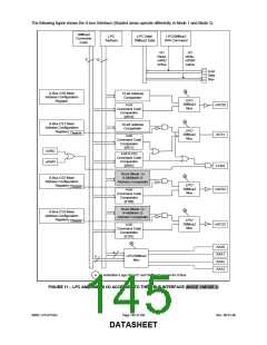
If a power button override was used to remove VCC, then only the power button can be used to return VCC power to
the system. See FIGURE 12 “Wakeup Logic” on page 149.
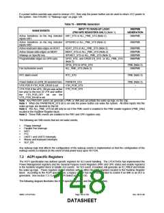
Table 78 − SMI/PME Generation
INPUT TO WAKE-UP LOGIC
SMI/PME
GENERATION
SMI/PME
WAKE EVENTS
(PM1/GPE REGISTERS ONLY) (Note 1)
Active transitions on the ring indicator nRI1_STS or ALL_PME_STS (Note 2)
inputs nRI1
Active transitions on the ring indicator GP50/RI2 or ALL_PME_STS (Note 2)
inputs nRI2
SMI/PME
Active keyboard-data edges on KDAT
Active mouse-data edges on MDAT
Wakeup on Specific key
KDAT_STS or ALL_PME_STS (Note 2)
MDAT_STS or ALL_PME_STS (Note 2)
SPEKEY_STS or ALL_PME_STS (Note 2)
SMI/PME
SMI/PME
SMI/PME
SMI/PME
Programmable edges on GPIO pins
GP23_STS, and GP[50:57]_STS or ALL_PME_STS
(Note 2)
GP34_STS & GP35_STS
ALL_PME_STS (Note 2)
PME (Note 3)
SMI/PME
Fan tachometer event
RTC alarm event
RTC_STS
PME (Note 3)
Power Button on (nPB_IN asserted low) PWRBTN_STS
VTR POR if VTR_POR_EN bit is set VTR_POR_STS
PME (Note 3)
−
−
VTR POR if the nPS_ON pin was active VTR_POR_STS
low prior to the loss of VTR and neither
the VTR_POR_OFF bit nor the
VTR_POR_EN bit is set
Note: Any PM1/GPE event can generate a PME or SMI and can initiate the wake-up logic on the chip.
Note 1: When the PWRBTNOR_STS bit is set only the power button can wake the system. All other inputs into the
wake-up logic are blocked by this bit.
Note 2: The ALL_PME_STS bit will only be set if the PME event is enabled in the PME enable registers (PME_ENx)
located in the Runtime Register block.
Note 3: These PME events are enabled in the PM1 and GPE registers only.
The following are SMI events that are not wake events:
Floppy Interrupt
Parallel Port Interrupt
WDT
P12
UART1 and UART2 interrupts
Mouse and keyboard interrupts
SLP_EN
Any wakeup logic that affects the configuration of the wakeup events is implemented so that the configuration of the
wakeup events is retained (in the event of total power loss) upon Vtr POR.
7.2 ACPI specific Registers
The ACPI specification has defined specific registers for SCI event handling. The LPC47S45x has implemented the
Power Management registers and the General Purpose Event Registers (PM1 and GPE status and enable registers)
in the Runtime Register block to handle SCI events. An SCI event, if enabled, will generate an IO_PME# and initiate
the wake-up logic. These registers do not interfere with or effect the PME registers located in the Runtime Register
block. According to the ACPI specification, a legacy switch has been incorporated to control if an SMI or an SCI is
generated. See section 7.3.1 Legacy/ACPI Select on page 150.
The following diagram illustrates the ACPI specific registers and the PME registers.
SMSC LPC47S45x
Page 148 of 259
Rev. 06-01-06
DATASHEET

 SMSC [ SMSC CORPORATION ]