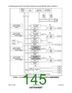
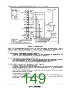
The following figure shows the X-bus Interface (Shaded areas operate differently in Mode 1 and Mode 2).
SMBus2
LPC
Address
LPC Data/
SMBus2 Data
LPC/SMBus2
R/W Command
Command
Code
I/O
I/O
Read-
nXRD
Active
Write-
nXWR
Active
8
12
8-bit
Data
Bus
a
X-Bus CS0 Base
12-bit Address
Address Configuration
Register
Comparator
LPC/
SMBus2
Mux
4-bit
nXCS0
XCS1
Command Code
Comparator
(0010)
a
X-Bus CS1 Base
Address Configuration
Register
10-bit Address
Comparator
LPC/
SMBus2
Mux
Disable
4-bit
Command Code
Comparator
(0011)
nXRD
nXWR
4-bit (LCD)
Command Code
Comparator
(0001)
LCDS
a
a
10-bit (Mode 1) /
10/8-bit Address
X-Bus CS2 Base
X-Bus CS2 Base
8-bit(Mode 2)
Address Configuration
Comparator
LPC/
Address Configuration
Register
Address Comparator
4-bit
Disable
Disable
LPC/
SMBus2
Register
nXCS2
nXCS2
SMBus2
Mux
4-bit
Command Code
Mux
Command Code
Comparator
Comparator
(0100)
(0100)
a
10/8-bit Address
X-Bus CS3 Base
10-bit (Mode 1) /
Comparator
Address Configuration
a
X-Bus CS3 Base
8-bit(Mode 2)
LPC/
SMBus2
Register
Disable
Address Configuration
Address Comparator
nXCS3
nXCS3
4-bit
Register
LPC/
Mux
Disable
Command Code
4-bit
SMBus2
Mux
Comparator
Command Code
(0101)
Comparator
(0101)
a
a
XAA0
XAA0
4
4
XAA1
XAA1
XAA2
XAA2
XAA3
XAA3
LPC/SMBus2
4
4
LPC/SMBus2
Mux
Mux
a
- Arbitration Logic for LPC and SMBus2 access for X-Bus
FIGURE 11 − LPC AND SMBUS I/O ACCESSES TO THE X-BUS INTERFACE (MODE 1/MODE 2)
SMSC LPC47S45x
Page 145 of 259
Rev. 06-01-06
DATASHEET

 SMSC [ SMSC CORPORATION ]