7
ACPI/PME/SMI FEATURES
The LPC47S45x supports ACPI as described in this section.
Note on Terminology in this Document:
A wake event results in the nPS_ON pin going active low.
A PME event results in the nIO_PME pin going active low.
The LPC47S45x supports legacy SMI events, power management events (PME) and the ACPI register set for SCI
event handling. The following sections will give an overview of the power supply states supported on the
LPC47S45x, the ACPI registers and features offered, and a description of PME and SMI event handling.
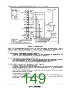
Note: The PM1 and GPE registers located in the Runtime Register block are ACPI specific registers used to support
SCI event handling. In addition, there is a Power Supply register in the Configuration Register block, Logical Device
A at offset 0xF8, that is used to control/enable the power supply states, sleep control, and the SMI/SCI select
capability for legacy support.
7.1 Power States
The ACPI Specification defines Global Sytem State Definitions, Device Power State Definitions, and Sleep State
definitions. The following sections show the power states that are supported in hardware by the LPC47S45x.
7.1.1 GLOBAL/SYSTEM SLEEP STATES
There are four Global System states and five System States as defined by the “Advanced Configuration and Power
Specification,” Rev 1.0b. Listed below are the supported Global and System states.
1. G3 – Mechanical Off (VCC=0V, VTR=0V)
This state is entered when power is totally removed from the system (i.e., pulling the plug). This is the only safe
state to operate on the hardware without damaging it. Except for the Real Time Clock, power consumption is
zero. See Table below for power supply states for “Mechanical Off”.
2. G2/S5 – Soft Off(VCC=0V, VTR=3.3V)
This state is entered when software writes a ‘1’ to the SLP_EN bit while the SLP_TYPx bits [4:2]=111. The
system can be awakened by the power button or a wake-up event (i.e., wake on specified key, RTC alarm, etc.).
This state is also entered when a power button over-ride event occurs, which is generated when a user presses
the power button for more than four seconds while the system is in the working state. If a power button over-ride
event is used to put the system into a Soft Off state, then the Power Button must be used to wake the system
from this state. The system will not respond to wake-up events. See section 7.3.2 Power Button With Override
on page 150.
3. G1/S4 – Sleeping(VCC=0V, VTR=3.3V)
This state is entered when software writes a ‘1’ to the SLP_EN bit while the SLP_TYPx bits [4:2]=110. The
system can be awakened by the power button or a wake-up event (i.e., wake on specified key, RTC alarm, etc.).
4. G0/S0 – Working (VCC=3.3V, VTR=3.3V)
All functional blocks are fully powered and operational in this state.
7.1.2 DEVICE SLEEP STATES
Each device in the LPC47S45x supports two device sleep states, D0 (on) and D3 (off). The D3 state corresponds to
the PCI defined D3 cold state. With all devices off, the part is powered either by main power (VCC) or by standby
power (VTR), depending on the system Sleep State. In both cases, the part can provide wakeup capability through
the power management logic and generate an IO_PME# or IO_SMI#. In an ACPI system, the devices are powered
on and off through control methods.
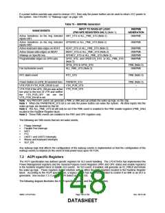
7.1.3 WAKE EVENTS
Wake events are events that turn power on (i.e. activate nPS_ON) if enabled. These events can be also enabled as
SMI, PME, or SCI events as shown in the following table.
It should be noted that all enabled SCI events in the PM1 and GPE1 registers will directly generate a signal into the
wakeup logic to turn on the power supply when VCC=0V, except if a power button override was used to turn VCC off.
SMSC LPC47S45x
Page 147 of 259
Rev. 06-01-06
DATASHEET

 SMSC [ SMSC CORPORATION ]