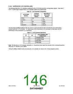
6.19.2 SUPPORTED LCD CONTROLLERS
The following table lists LCD controllers supported by the LPC47S45x and their corresponding signals. Chip select 1,
XCS1, is active high to support these LCD controllers without any external logic.
Table 76 − LCD Controller Connections
HITACHI
HD61202U
SIGNAL
MOTOROLA
MC141803
SIGNAL
LPC47S45X
SIGNAL
XCS1
CS3
E
CE
LCDCS
A0
CS#
RW
D/I
R/W#
D/C#
DO-D7
A1
XD0-XD7
DB0-DB7
The two least significat address bits are used to communicate the type and direction of a transaction
initiated with the LCD controller. A1 determines if the transaction is a command or data type and A0
determines is the transaction is a read/write.
Table 77 − LCD Controller Operations
LCD CONTROLLER
A1
A0
OPERATION
0
0
1
1
0
1
0
1
Command Write
Command Read
Data Write
Data Read
Note: The direction of LCD Controller Operation (i.e. Read/Write) must match the direction of the command issued by
either the LPC interface or the SMBus.
Timing for SMBus initiated cycles accessing the LCD controller are shown in the Timing Diagrams section.
SMSC LPC47S45x
Page 146 of 259
Rev. 06-01-06
DATASHEET

 SMSC [ SMSC CORPORATION ]