6.18.4 SMBUS2 REGISTER SUMMARY
SMBus2 has a dedicated set of registers, accessible by the SMBus, that are used for disabling peripheral devices,
arbitrating X-Bus access, and monitoring the length of time VCC and VTR are powered-on. These registers are listed
in the following table. Notice that VCC_CNTx and VTR_CNTx are also accessible by the LPC interface through the
runtime registers (See section 8 Runtime Registers on page 156).
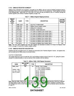
Table 71 − SMBus2 Register Mapping Summary
SMBUS2
RUNTIME
REG
NAME
TYPE
DESCRIPTION
REGISTER
OFFSET
OFFSET
(HEX)
00
SMB_Com2
SMB_DDR
SMB_ARB
Reserved
R/W
R/W
R/W
R/W
R
Com Port 2 Enable/Disable
-
01
02
03
04
05
06
07
08
09
0A
0B
SMBus2 Device Disable Control
-
SMBus2/LPC Arbitration
-
Reserved – Reads return zero.
-
Vcc_CNT1
Vcc_CNT2
Vcc_CNT3
Vcc_CNT4
Vtr_CNT1
Vtr_CNT2
Vtr_CNT3
Vtr_CNT4
Vcc Power On Elapsed Time Counter, Byte 1
Vcc Power On Elapsed Time Counter, Byte 2
Vcc Power On Elapsed Time Counter, Byte 3
Vcc Power On Elapsed Time Counter, Byte 4
Vtr Power On Elapsed Time Counter, Byte 1
Vtr Power On Elapsed Time Counter, Byte 2
Vtr Power On Elapsed Time Counter, Byte 3
Vtr Power On Elapsed Time Counter, Byte 4
6Dh
6Eh
6Fh
70h
71h
72h
73h
74h
R
R
R
R
R
R
R
Note: The VCC_CNTx registers and VTR_CNT registers are described in section 6.14 Power On Elapsed Timer
(POET) on page 123 and in the Runtime Register section.
6.18.5 SMBUS2 REGISTER DESCRIPTION
Registers that are accessible by the LPC interface are described in the “Runtime Register” Section. All registers that
are accessible by the SMBus only are described below.
Com Port 2 Enable/Disable
This register allows the user to tri-state the Com 2 port interface located on pins 93 and 95 to 101, giving the system
designer the added flexability to mux an external COM Controller with this interface.
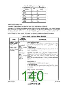
Table 72 − SMBus 2 SMB_COM2 Register Description
REG OFFSET
NAME
TYPE
DESCRIPTION
Bit [0] = Com 2 Disable
(HEX)
SMB_Com2
00h
I/O
0 = Com 2 Interface Enabled
1 = Com 2 Interface Disabled
Bit [1] = Reserved
Default = 0x00
on VCC POR
and PCI Reset.
Bit [2] = Reserved
Bit [3] = Reserved
Bit [4] = Reserved
Bit [5] = Reserved
Bit [6] = Reserved
Bit [7] = Reserved
Note: When the SMB_COM2, Bit [0] = 1, all COM Port 2 input pins are disconnected from the COM Port 2 controller.
All output buffers on the COM Port 2 interface pins (i.e., pins 93, 95-101) are tri-stated, regardless of whether they
are configured for GPIO or UART functionality. The Com Port 2 input pins are held in an inactive state as described
in Table 73.
SMSC LPC47S45x
Page 139 of 259
Rev. 06-01-06
DATASHEET

 SMSC [ SMSC CORPORATION ]