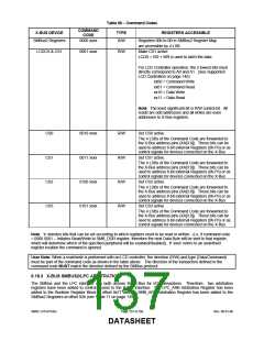
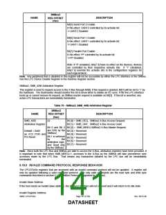
Table 69 − Command Codes
COMMAND
CODE
X-BUS DEVICE
TYPE
REGISTERS ACCESSIBLE
SMBus2 Registers
0000 xxxx
R/W
R/W
Registers 00h to 0B in SMBus2 Register Map
are accessible by 4 LSB.
LCDCS & CS1
0001 xxxx
Make CS1 active
LCDS = RD + WR is used to latch the data.
For LCD Controller operation, the 2 lowest bits must
directly correspond to A0 and A1. (See Supported
LCD Controllers on page 146)
xx00 = Command Write
xx01 = Command Read
xx10 = Data Write
xx11 = Data Read
Note: The least significant bit is R/W control bit. All
reads are odd addresses and all writes are even
addresses to X-Bus registers.
CS0
CS1
CS2
CS3
0010 xxxx
0011 xxxx
0100 xxxx
0101 xxxx
R/W
R/W
R/W
R/W
Set CS0 active.
The 4 LSBs of the Command Code are forwarded to
the X-Bus address pins (XA[3:0]). These bits can be
used to address 8-bit external Registers (0h-Fh) or as
control signals for devices connected on the X-Bus
Set CS1 active.
The 4 LSBs of the Command Code are forwarded to
the X-Bus address pins (XA[3:0]). These bits can be
used to address 8-bit external Registers (0h-Fh) or as
control signals for devices connected on the X-Bus
Set CS2 active.
The 4 LSBs of the Command Code are forwarded to
the X-Bus address pins (XA[3:0]). These bits can be
used to address 8-bit external Registers (0h-Fh) or as
control signals for devices connected on the X-Bus
Set CS3 active.
The 4 LSBs of the Command Code are forwarded to
the X-Bus address pins (XA[3:0]). These bits can be
used to address 8-bit external Registers (0h-Fh) or as
control signals for devices connected on the X-Bus
Note: ‘x’ denotes bits that can be set according to which registers need to be read or written. (i.e. if command code
= 0000 0001 – Initiates Read/Write to SMB_DDR register, therefore the next Data Byte will be sent to that register,
which will determine which of the specified peripheral will be enabled/disabled). If ‘xxxx’ refers to an undefined
register location the command is ignored.
User Note: When a read/write is performed with an LCD controller, the direction (R/W) and type (Data/Command)
must be part of the command code as shown in the table above. The direction of the transaction defined in the
command code MUST match the direction defined by the SMBus protocol.
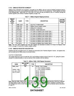
6.18.3 X-BUS SMBUS2/LPC ARBITRATION
The SMBus and the LPC interface can both access the X-Bus for I/O transactions. Therefore, two arbitration
registers have been added to control access to the X-Bus interface. The LPC_ARB Arbitration Register has been
added to the Runtime Register Block at offset 0x77 and the SMB_ARB Arbitration Register has been added to the
SMBus2 Registers at offset 02h (see Table 71 on page 139).
SMSC LPC47S45x
Page 137 of 259
Rev. 06-01-06
DATASHEET

 SMSC [ SMSC CORPORATION ]