Bit 0 nBB
Bus Busy bit. This is a read-only flag indicating when the SMBus is in use. A zero indicates that the bus is busy, and
access is not possible. This bit is set/reset (logic “1”/logic “0”) by Start/Stop conditions.
Own Address Register
When the chip is addressed as slave, this register must be loaded with the 7-bit SMBus address to which the chip is
to respond. During initialization, the own address register must be written to, regardless whether it is later used. The
Addressed As Slave (AAS) bit in status register is set when this address is received (the value in the data register is
compared with the value in own address register). Note that the data and own address registers are offset by one bit;
hence, programming the own address register with a value of 55h will result in the value AAh being recognized as the
chip’s SMBus slave address.
After reset, own address register has default address 00h.
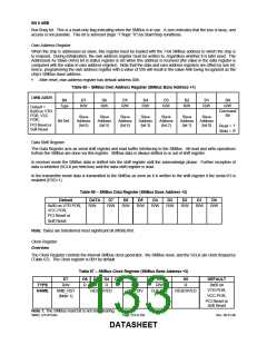
Table 65 − SMBus Own Address Register (SMBus Base Address +1)
OWN ADDR
Bit
D7
D6
D5
D4
D3
D2
D1
D0
Type
R/W
R/W
R/W
R/W
R/W
R/W
R/W
R/W
Default =
0x00 on VTR
POR, VCC
POR,
Command
Bit
Slave
Address
(bit 6)
Slave
Address
(bit 5)
Slave
Address
(bit 4)
Slave
Address
(bit 3)
Slave
Address
(bit 2)
Slave
Address
(bit 1)
Slave
Address
(bit 0)
Bit Def
PCI Reset or
Soft Reset
Read = ‘1’
Write = ‘0’
Data Shift Register
The Data Register acts as serial shift register and read buffer interfacing to the SMBus. All read and write operations
to/from the SMBus are done via this register. SMBus data is always shifted in or out of shift register.
In receiver mode the SMBus data is shifted into the shift register until the acknowledge phase. Further reception of
data is inhibited (SCLK pin held low) until the data shift register is read.
In the transmitter mode data is transmitted to the SMBus as soon as it is written to the shift register if the serial I/O is
enabled (ESO=1).
Table 66 − SMBus Data Register (SMBus Base Address +2)
Default
DATA
D7
D6
D5
D4
D3
D2
D1
D0
0x00 on VTR POR,
VCC POR,
R/W
R/W
R/W
R/W
R/W
R/W
R/W
R/W
R/W
PCI Reset or
Soft Reset
Note: Bytes are transferred most significant bit (MSB) first.
Clock Register
Overview
The Clock Register controls the internal SMBus clock generator, the SMBus reset, and the SCLK pin clock frequency
(Table 67). The Clock register is 00H by default.
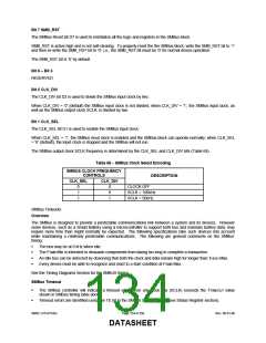
Table 67 − SMBus Clock Register (SMBus Base Address +3)
D7
D6 D5 D4 D3
D2
R/W
D1
R/W
D0
R
DEFAULT
0x00 on
TYPE
R/W
R
R
R
R
VTR POR,
VCC POR,
NAME
SMB_RST
(Note 1)
RESERVED
CLK_DIV
CLK_SEL
RESERVED
PCI Reset or
Soft Reset
Note 1: The SMBus reset bit is not self-clearing.
SMSC LPC47S45x
Page 133 of 259
Rev. 06-01-06
DATASHEET

 SMSC [ SMSC CORPORATION ]