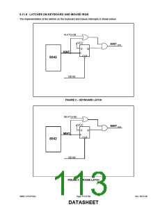
expansion, the LPC47S45x provides four signal pins that may be used to implement this interface directly for an external
keyboard and mouse.
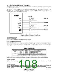
The LPC47S45x has four high-drive, open-drain output, bidirectional port pins that can be used for external serial
interfaces, such as external keyboard and PS/2-type mouse interfaces. They are KCLK, KDAT, MCLK, and MDAT. P26
is inverted and output as KCLK. The KCLK pin is connected to TEST0. P27 is inverted and output as KDAT. The
KDAT pin is connected to P10. P23 is inverted and output as MCLK. The MCLK pin is connected to TEST1. P22 is
inverted and output as MDAT. The MDAT pin is connected to P11. NOTE: External pull-ups may be required.
6.11.3 KEYBOARD POWER MANAGEMENT
The keyboard provides support for two power-saving modes: soft powerdown mode and hard powerdown mode. In soft
powerdown mode, the clock to the ALU is stopped but the timer/counter and interrupts are still active. In hard power
down mode the clock to the 8042 is stopped.
Soft Power Down Mode
This mode is entered by executing a HALT instruction. The execution of program code is halted until either RESET is
driven active or a data byte is written to the DBBIN register by a master CPU. If this mode is exited using the interrupt,
and the IBF interrupt is enabled, then program execution resumes with a CALL to the interrupt routine, otherwise the
next instruction is executed. If it is exited using RESET then a normal reset sequence is initiated and program execution
starts from program memory location 0.
Hard Power Down Mode
This mode is entered by executing a STOP instruction. The oscillator is stopped by disabling the oscillator driver
cell. When either RESET is driven active or a data byte is written to the DBBIN register by a master CPU, this mode will
be exited (as above). However, as the oscillator cell will require an initialization time, either RESET must be held active
for sufficient time to allow the oscillator to stabilize. Program execution will resume as above.
6.11.4 INTERRUPTS
The LPC47S45x provides the two 8042 interrupts: IBF and the Timer/Counter Overflow.
6.11.5 MEMORY CONFIGURATIONS
The LPC47S45x provides 2K of on-chip ROM and 256 bytes of on-chip RAM.
6.11.6 REGISTER DEFINITIONS
Host I/F Data Register
The Input Data register and Output Data register are each 8 bits wide. A write to this 8 bit register will load the
Keyboard Data Read Buffer, set the OBF flag and set the KIRQ output if enabled. A read of this register will read the
data from the Keyboard Data or Command Write Buffer and clear the IBF flag. Refer to the KIRQ and Status register
descriptions for more information.
Host I/F Status Register
The Status register is 8 bits wide. Table 54 shows the contents of the Status register.
Table 54 − Status Register
D7
D6
D5
D4
D3
D2
D1
D0
UD
UD
UD
UD
C/D
UD
IBF
OBF
Status Register
This register is cleared on a reset. This register is read-only for the Host and read/write by the LPC47S45x CPU.
UD
Writable by LPC47S45x CPU. These bits are user-definable.
C/D
(Command Data)-This bit specifies whether the input data register contains data or a command (0 = data, 1 =
command). During a host data/command write operation, this bit is set to "1" if SA2 = 1 or reset to "0" if SA2 =
0.
IBF
(Input Buffer Full)- This flag is set to 1 whenever the host system writes data into the input data register.
Setting this flag activates the LPC47S45x CPU's nIBF (MIRQ) interrupt if enabled. When the LPC47S45x CPU
SMSC LPC47S45x
Page 110 of 259
Rev. 06-01-06
DATASHEET

 SMSC [ SMSC CORPORATION ]