periodic interrupt, but the periodic flag (PF) is still
set at the periodic rate. PIE is not modified by
any internal function, but is cleared to "0" by a
RESET_DRV.
RES
Reserved - read as “0”.
DM
The data mode bit indicates whether time and
calendar updates are to use binary or BCD
formats. The DM bit is written by the processor
program and may be read by the program, but
is not modified by any internal functions or by
RESET_DRV. A "1" in DM signifies binary data,
while a "0" in DM specifies BCD data.
AIE
The alarm interrupt enable bit is a read/write bit,
which when set to a "1" permits the alarm flag (AF)
bit in Register C to assert IRQB. An alarm
interrupt occurs for each second that the three
time Bytes equal the three alarm bytes (including a
"don't care" alarm code of binary 11XXXXXX).
When the AIE bit is a "0", the AF bit does not
initiate an IRQB signal. The RESET_DRV port
clears AIE to
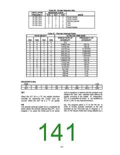
24/12
The 24/12 control bit establishes the format of the
hours byte as either the 24 hour mode if set to a
"1", or the 12 hour mode if cleared to a "0". This
is a read/write bit which is not affected by
RESET_DRV or any internal function.
"0". The AIE bit is not affected by any internal
functions.
UIE
The update-ended interrupt enable bit is
a
DSE
read/write bit which enables the update-end flag
(UF) bit in Register C to assert IRQB. The
RESET_DRV port or the SET bit going high clears
the UIE bit.
The daylight savings enable bit is read only and is
always set to a "0" to indicate that the daylight
savings time option is not available.
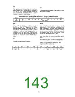
REGISTER C (CH) - READ ONLY REGISTER
MSB
LSB
b7
IRQF
b6
PF
b5
AF
b4
UF
b3
0
b2
0
b1
0
b0
0
on the selected tap of the divider chain. The
RS3-RS0 bits establish the periodic rate. PF is set
to a "1" independent of the state of the PIE bit.
PF being a "1" sets the IRQF bit and initiates an
IRQB signal when PIE is also a "1". The PF bit is
cleared by RESET_DRV or by a read of Register
C .
IRQF
The interrupt request flag is set to a "1" when one
or more of the following are true:
PF = PIE = 1
AF = AIE = 1
UF = UIE = 1
AF
Any time the IRQF bit is a "1", the IRQB signal is
driven low. All flag bits are cleared after Register
C is read or by the RESET_DRV port.
The alarm interrupt flag when set to a "1" indicates
that the current time has matched the alarm time.
A "1" in AF causes a "1" to appear in IRQF and the
IRQB port to go low when the AIE bit is also a "1".
A RESET_DRV or a read of Register C clears the
AF bit.
PF
The periodic interrupt flag is a read-only bit which
is set to a "1" when a particular edge is detected
145

 SMSC [ SMSC CORPORATION ]