SOFT POWER MANAGEMENT
This chip employs soft power management to
section. The chip can also be programmed to
always stay off when the AC power returns. (See
VTR_POR_OFF in the RTC section.)
allow the chip to enter low power mode and to
provide a variety of wakeup events to power up
the chip. This technique allows for software
control over powerdown and wakeup events. In
low power mode, the chip runs off of the trickle
voltage, VTR. In this mode, the chip is ready to
power up from either the power button or from one
of a number of wakeup events including pressing a
key, touching the mouse or receiving data from
one of the UARTs. The alarm can also be set to
power up the system at a predetermined time to
perform one or more tasks.
The Button input can be used to turn off the power
supply after a debounce delay. The power supply
can also be turned off under software control (via a
write to register WDT_CTRL with bit 7 set).
Configuration registers L8-CR_B0 and L8-
CR_B1 select the wakes-up events (SPx). The
Configuration registers L8-CR_B2 and L8-
CR_B3 indict the wake-up event status. The
possible wake-events are:
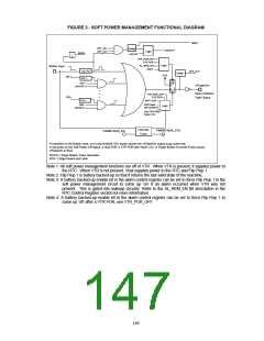
The implementation of Soft Power Management is
illustrated in Figure 11. A high to low transition on
the Button input or on any of the enabled wakeup
events (SPx) causes the nPowerOn output to go
active low which turns on the main power supply.
Even if the power supply is completely lost (i.e.,
VTR is not present) the power supply can still be
turned on upon the return of VTR. This is
accomplised by an alarm event that has already
passed (if the alarm remember bit is enabled) or
by a VTR power on reset (if the VTR POR bit is
enabled). These bits are described in the RTC
•
•
•
•
•
•
•
•
•
•
UART1 and UART 2 Ring Indicator Pin
Keyboard and Mouse clock Pin
Group Interrupt 1, Group Interrupt 2
IRRX2 input pin
RTC Alarm
UART 1 and UART 2 Receive Data Pin
nRING pin
Consumer IR (CIR)
Power Button input pin
VTR_POR
148

 SMSC [ SMSC CORPORATION ]