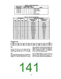
Table 66 - Divider Selection Bits
REGISTER A BITS
OSCILLATOR
FREQUENCY
32.768 KHz
32.768 KHz
32.768 KHz
32.768 KHz
32.768 KHz
DV2
0
0
DV1
0
0
DV0
0
1
MODE
Reset Divider
Reset Divider
0
0
1
1
0
1
Normal Operate
Test
1
0
X
Test
1
1
X
Reset Divider
Table 67 - Periodic Interrupt Rates
32.768 KHz TIME BASE
RATE SELECT
PERIOD RATE OF
INTERRUPT
0.0
FREQUENCY OF
INTERRUPT
RS3
0
RS2
0
RS1
0
RS0
0
0
0
0
0
0
0
0
1
0
0
0
1
1
1
1
0
0
1
1
0
0
1
1
0
1
0
1
0
1
0
1
0
3.90625 ms
7.8125 ms
122.070 μs
244.141 μs
488.281 μs
976.562 μs
1.953125 ms
3.90625 ms
7.8125 ms
15.625 ms
31.25 ms
256 Hz
128 Hz
8.192 KHz
4.096 KHz
2.048 KHz
1.024 KHz
512 Hz
256 Hz
128 Hz
64 Hz
1
1
1
0
0
0
0
1
1
1
0
1
32 Hz
1
1
0
0
62.5 ms
16 Hz
1
1
0
1
125 ms
8 Hz
1
1
1
0
250 ms
4 Hz
1
1
1
1
500 ms
2 Hz
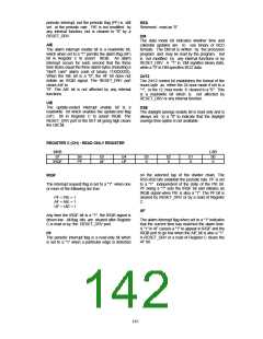
REGISTER B (BH)
MSB
b7
SET
LSB
b0
DSE
b6
PIE
b5
AIE
b4
UIE
b3
RES
b2
DM2
b1
24/12
cycle in progress is aborted and the program may
initialize the time and calendar bytes without an
update occurring in the middle of initialization.
SET is a read/write bit which is not modified by
RESET_DRV or any internal functions.
SET
When the SET bit is a "0", the update functions
normally by advancing the counts once per
second. When the SET bit is a "1", an update
low. The program writes a "1" to the PIE bit in
order to receive periodic interrupts at the rate
specified by the RS3-RS0 bits in Register A. A
zero in PIE blocks IRQB from being initiated by a
PIE
The periodic interrupt enable bit is a read/write bit
which allows the periodic-interrupt flag (PF) bit in
Register C to cause the IRQB port to be driven
143

 SMSC [ SMSC CORPORATION ]