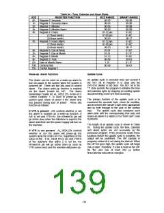
Table 64 - Time, Calendar and Alarm Bytes
REGISTER FUNCTION BCD RANGE
Register 0: Seconds
ADD
0h
1h
2h
3h
BINARY RANGE
00-3B
00-59
00-59
Register 1: Seconds Alarm
Register 2: Minutes
Register 3: Minutes Alarm
Register 4: Hours
00-3B
00-3B
00-3B
01-0C
81-8C
00-17
00-59
00-59
01-12 am
81-92 pm
00-23
4h
(12 hour mode)
(24 hour mode)
5h
Register 5: Hours Alarm
(12 hour mode)
01-12 am
81-92 pm
00-23
01-0C
81-8C
00-17
(24 hour mode)
6h
7h
8h
9h
Dh
Register 6: Day of Week
Register 7: Day of Month
Register 8: Month
Register 9: Year
Date of Month Alarm
01-07
01-31
01-12
00-99
01-07
01-1F
01-0C
00-63
01-1F
1-31
7Dh Century Byte
00-99
00-63
7Eh
Control Register 1
Wake-up Alarm Function
Update Cycle
An update cycle is executed once per second if
the SET bit in Register B is clear and the
DV0-DV2 divider is not clear. The SET bit in the
"1" state permits the program to initialize the time
and calendar bytes by stopping an existing update
and preventing a new one from occurring.
The Alarm can be used as a wake-up alarm to
turn on power to the system when the system is
powered off. There are two bits used to control
alarm. The Alarm wake-up function is enabled
via the Alarm Enable bit, AIE. The Alarm
Remember Enable bit, AL_REM_EN, in the RTC
Control Register 1, is used to power-up the
system upon return of power if the Alarm time
has passed during loss of power. These bits
function as follows:
The primary function of the update cycle is to
increment the seconds’ byte, check for overflow,
and increment the minute’s byte when appropriate
and so forth through to the year of the century
byte.
The update cycle also compares each
If VTR is present: AIE controls whether or not
the alarm is enabled as a wake-up function. If
AIE is set and VTR=5V, the nPowerOn pin will
go active (low) when the date/time is equal to the
alarm date/time and the power supply will turn on
the machine.
alarm byte with the corresponding time byte and
issues an alarm if a match or if a "don't care" code
is present.
The length of an update cycle is shown in Table
65. During the update cycle, the time, calendar
and alarm bytes are not accessible by the
processor program. If the processor reads these
locations before the update cycle is complete, the
output will be undefined. The UIP (update in
progress) status bit is set during the interval. When
the UIP bit goes high, the update cycle will begin
244 μs later. Therefore, if a low is read on the UIP
bit, the user has at least 244 μs before
time/calendar data will be changed.
If VTR is not present: AL_REM_EN controls
whether or not the alarm will power-up the
system upon the return of VTR, regardless of the
value of AIE. If AL_REM_EN is set and VTR=0
at the date/time that alarm 2 is set for, the
nPowerOn pin will go active (low) as soon as
VTR comes back and the machine will power-up.
141

 SMSC [ SMSC CORPORATION ]