1. Registers 00-0D are initialized to 00h.
2. Access to all registers from the host are
blocked.
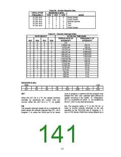
The RTC Interrupt is brought out by programming
the RTC Primary Interrupt Select to a non-zero
value. If IRQ 8 is selected then the polarity of this
IRQ 8 output is programmable through a bit in the
OSC Global Configuration Register.
RTC Interrupt
The interrupt generated by the RTC is an active
high output. The RTC interrupt output remains
high as long as the status bit causing the interrupt
is present and the corresponding interrupt-enable
bit is set. Activating RESET_DRV or reading
register C clears the RTC interrupt.
Internal Registers
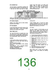
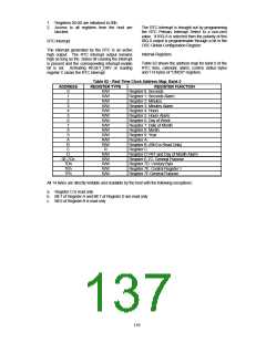
Table 62 shows the address map for bank 0 of the
RTC; time, calendar, alarm, control, status bytes
and 114 bytes of "CMOS" registers.
Table 62 - Real Time Clock Address Map, Bank 0
ADDRESS
REGISTER TYPE
R/W
REGISTER FUNCTION
Register 0: Seconds
0
1
2
R/W
R/W
Register 1: Seconds Alarm
Register 2: Minutes
3
4
R/W
R/W
Register 3: Minutes Alarm
Register 4: Hours
5
6
7
8
R/W
R/W
R/W
R/W
Register 5: Hours Alarm
Register 6: Day of Week
Register 7: Date of Month
Register 8: Month
9
R/W
Register 9: Year
A
R/W
Register A:
B
C
R/W
R
Register B: (Bit 0 is Read Only)
Register C:
D
R/W
R/W
R/W
R/W
Register D:VRT and Day of Month Alarm
Register E-7C: General Purpose
Register 7D: Century Byte
Register 7E: Control Register 1
Register 7F:General Purpose
0E-7Ch
7Dh
7Eh
7Fh
R/W
All 14 bytes are directly writable and readable by the host with the following exceptions:
a. Register C is read only
b. Bit 7 of Register A and Bit 7 of Register D are read only
c. Bit 0 of Register B is read only
139

 SMSC [ SMSC CORPORATION ]