Fan Control Device with High Frequency PWM Support and Hardware Monitoring Features
Datasheet
cycle. If the current PWM duty cycle is equal to the calculated duty cycle the PWM output will remain
unchanged.
Internally, the PWM Ramp Rate Control Logic will increment/decrement the internal PWM Duty cycle
by ‘1’ at a rate determined by the Ramp Rate Control Register (see Register 62h, 63h: PWM Ramp
Rate Control on page 69). The actual duty cycle output is changed once per the period of the PWM
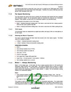
output, which is determined by the frequency of the PWM output. (See Figure 7.4 Illustration of PWM
Ramp Rate Controlon page 41.)
■
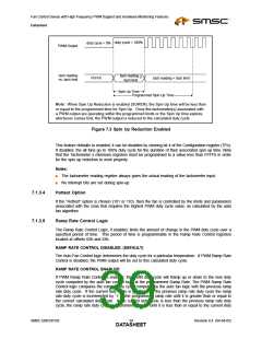
If the period of the PWM output is less than the step size created by the PWM Ramp Rate, the
PWM output will hold the duty cycle constant until the Ramp Rate logic increments/decrements the
duty cycle by ‘1’ again. For example, if the PWM frequency is 87.7Hz (1/87.7Hz = 11.4msec) and
the PWM Step time is 206msec, the PWM duty cycle will be held constant for a minimum of 18
periods (206/11.4 = 18.07) until the Ramp Logic increments/decrements the actual PWM duty cycle
by ‘1’.
■
If the period of the PWM output is greater than the step size created by the PWM Ramp Rate, the
ramp rate logic will force the PWM output to increment/decrement the actual duty cycle in
increments larger than 1/255. For example, if the PWM frequency is 11Hz (1/11Hz = 90.9msec)
and the PWM Step time is 5msec, the PWM duty cycle output will be incremented 18 or 19 out of
255 (i.e., 90.9/5 = 18.18) until it reaches the calculated duty cycle.
Notes:
■
The step size may be less if the calculated duty cycle minus the actual duty cycle is less than 18.
■
The calculated PWM Duty cycle reacts immediately to a change in the temperature reading value.
The temperature reading value may be updated once in 624msec, once in 78msec, once in
223msec (default), or once in 447msec (see Table 6.2, “Conversion Cycle Timing,” on page 24).
The internal PWM duty cycle generated by the Ramp Rate control logic gradually ramps up/down
to the calculated duty cycle at a rate pre-determined by the value programmed in the PWM Ramp
Rate Control bits . The PWM output latches the internal duty cycle generated by the Ramp Rate
Control Block every 1/(PWM frequency) seconds to determine the actual duty cycle of the PWM
output pin.
PWM Output Transition from OFF to ON
When the calculated PWM Duty cycle generated by the auto fan control logic transitions from the ‘OFF’
state to the ‘ON’ state (i.e., Current PWM duty cycle>00h), the internal PWM duty cycle in the Ramp
Rate Control Logic is initialized to the calculated duty cycle without any ramp time and the PWMx
Current Duty Cycle register is set to this value. The PWM output will latch the current duty cycle value
in the Ramp Rate Control block to control the PWM output.
PWM Output Transition from ON to OFF
Each PWM output has a control bit to determine if the PWM output will transition immediately to the
OFF state (default) or if it will gradually step down to Off at the programmed Ramp Rate. These control
bits (SZEN) are located in the PWMx Options registers at offsets 94h-96h.
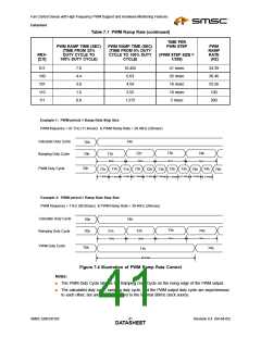
Table 7.1 PWM Ramp Rate
TIME PER
PWM RAMP TIME (SEC)
(TIME FROM 33%
PWM RAMP TIME (SEC)
(TIME FROM 0% DUTY
CYCLE TO 100% DUTY
CYCLE)
PWM STEP
PWM
RAMP
RATE
(HZ)
RRX-
[2:0]
DUTY CYCLE TO
(PWM STEP SIZE =
1/255)
100% DUTY CYCLE)
000
001
010
35
52.53
26.52
206 msec
104 msec
69 msec
4.85
9.62
17.6
11.8
17.595
14.49
Revision 0.4 (04-04-05)
SMSC EMC6D103
DATA4S0HEET

 SMSC [ SMSC CORPORATION ]