Fan Control Device with High Frequency PWM Support and Hardware Monitoring Features
Datasheet
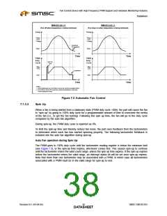
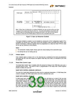
duty cycle = 100%
duty cycle = 0%
PWM Output
tach reading
vs. tach limit
tach reading >
tach limit
FFFFh
tach reading < tach limit
Spin Up Time
Programmed Spin Up Time
Note: When Spin Up Reduction is enabled (SUREN), the Spin Up time will be less than
or equal to the programmed time for Spin Up. Once the tachometer(s) associated with
a PWM output are operating within the programmed limits or the Spin Up time expires,
whichever comes first, the PWM output is reduced to the calculated duty cycle.
Figure 7.3 Spin Up Reduction Enabled
This feature defaults to enabled; it can be disabled by clearing bit 4 of the Configuration register (7Fh).
If disabled, the all fans go to 100% duty cycle for the duration of their associated spin up time. Note
that the Tachometer x minimum registers must be programmed to a value less than FFFFh in order
for the spin up reduction to work properly.
Notes:
■
The tachometer reading register always gives the actual reading of the tachometer input.
No interrupt bits are set during spin-up.
■
7.1.3.4
7.1.3.5
Hottest Option
If the “Hottest” option is chosen (101 or 110), then the fan is controlled by the limits and parameters
associated with the zone that requires the highest PWM duty cycle value, as calculated by the auto
fan algorithm.
Ramp Rate Control Logic
The Ramp Rate Control Logic, if enabled, limits the amount of change in the PWM duty cycle over a
specified period of time. This period of time is programmable in the Ramp Rate Control registers
located at offsets 62h and 63h.
RAMP RATE CONTROL DISABLED: (DEFAULT)
The Auto Fan Control logic determines the duty cycle for a particular temperature. If PWM Ramp Rate
Control is disabled, the PWM output will be set to this calculated duty cycle.
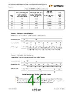
RAMP RATE CONTROL ENABLED:
If PWM Ramp Rate Control is enabled, the PWM duty cycle will Ramp up or down to the new duty
cycle computed by the auto fan control logic at the programmed Ramp Rate. The PWM Ramp Rate
Control logic compares the current duty cycle computed by the auto fan logic with the previous ramp
rate duty cycle. If the current duty cycle is greater than the previous ramp rate duty cycle the ramp
rate duty cycle is incremented by ‘1’ at the programmed ramp rate until it is greater than or equal to
the current calculated duty cycle. If the current duty cycle is less than the previous ramp rate duty
cycle, the ramp rate duty cycle is decremented by ‘1’ until it is less than or equal to the current duty
SMSC EMC6D103
Revision 0.4 (04-04-05)
DATA3S9HEET

 SMSC [ SMSC CORPORATION ]