Fan Control Device with High Frequency PWM Support and Hardware Monitoring Features
Datasheet
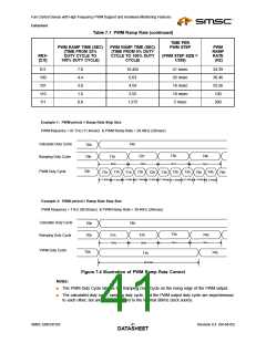
Table 7.1 PWM Ramp Rate (continued)
TIME PER
PWM RAMP TIME (SEC)
(TIME FROM 33%
PWM RAMP TIME (SEC)
(TIME FROM 0% DUTY
CYCLE TO 100% DUTY
CYCLE)
PWM STEP
PWM
RAMP
RATE
(HZ)
RRX-
[2:0]
DUTY CYCLE TO
(PWM STEP SIZE =
1/255)
100% DUTY CYCLE)
011
100
101
110
111
7.0
4.4
3.0
1.6
0.8
10.455
6.63
41 msec
26 msec
18 msec
10 msec
5 msec
24.39
38.46
55.56
100
4.59
2.55
1.275
200
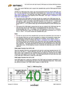
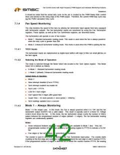
Example 1: PWM period < Ramp Rate Step Size
PWM frequency = 87.7Hz (11.4msec) & PWM Ramp Rate = 38.46Hz (26msec)
Calculate Duty Cycle
Ramping Duty Cycle
74h
70h
70h
73h
72h
74h
71h
26ms
26ms
26ms
26ms
PWM Duty Cycle
70h
71h
72h
73h
73h
74h
71h
71h
72h
73h
74h
74h
11.4ms
11.4ms
11.4ms
11.4ms
11.4ms
11.4ms
11.4ms
11.4ms
11.4ms
Example 2: PWM period > Ramp Rate Step Size
PWM frequency = 11Hz (90.9msec) & PWM Ramp Rate = 38.46Hz (26msec)
Calculate Duty Cycle
Ramping Duty Cycle
74h
70h
70h
73h
72h
74h
71h
26ms
26ms
26ms
26ms
PWM Duty Cycle
70h
74h
71h
90.9msec
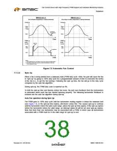
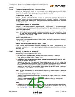
Figure 7.4 Illustration of PWM Ramp Rate Control
Notes:
■
The PWM Duty Cycle latches the Ramping Duty Cycle on the rising edge of the PWM output.
■
The calculated duty cycle, ramping duty cycle, and the PWM output duty cycle are asynchronous
to each other, but are all synchronized to the internal 90kHz clock source.
SMSC EMC6D103
Revision 0.4 (04-04-05)
DATA4S1HEET

 SMSC [ SMSC CORPORATION ]