Fan Control Device with High Frequency PWM Support and Hardware Monitoring Features
Datasheet
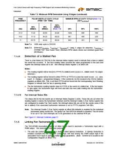
register is updated with that count value. If the counter reaches FFFFh and no edges were detected
a stalled fan event has occurred and the Tach Reading register will be set to FFFFh. If one or more
edges are detected, but less than the programmed number of edges, a slow fan event has occurred
and the Tach Reading register will be set to either FFFEh or FFFFh depending on the state of the Slow
Tach bits located in the TACHx Options registers at offsets 90h - 93h. Software can easily compute
the RPM value using the tachometer reading value if it knows the number of edges per revolution.
7.1.4.4 Mode 2 – Monitor Tach input When PWM is ‘ON’
In this mode, the PWM is used to pulse the Fan motor of a 3-wire fan. 3-wire fans use the same
power supply to drive the fan motor and to drive the tachometer output logic. When the PWM is ‘ON’
the fan generates valid tach pulses. When the PWM is not driving the Fan, the tachometer signal is
not generated and the tach signal becomes indeterminate or tristate. Therefore, Mode 2 only makes
tachometer measurements when the associated PWM is driving high during an update cycle. As a
result, the Fan tachometer measurement is “synchronized” to the PWM output, such that it only looks
for tach pulses when the PWM is ‘ON’.
Notes:
■
High frequency PWM operation is designed for use with four wire fans. Although some three wire
fans are capable of operating with high frequency PWM, the tach output is very difficult to read.
External circuitry is required for accurate tach reading of a three wire fan that is driven with high
frequency PWM.
■
Any fan tachometer input may be associated with any PWM output (see Linking Fan Tachometers
to PWMs on page 47.)
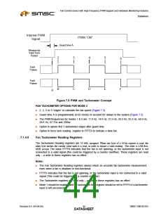
ASSUMPTIONS (REFER TO FIGURE 7.5, "PWM AND TACHOMETER CONCEPT"):
The Tachometer pulse generates 5 transitions per fan revolution (i.e., two fan tachometer periods per
revolution, edges 2→6). One half of a revolution (one tachometer period) is equivalent to three edges
(2→4 or 3→5). One quarter of a revolution (one-half tachometer period) is equivalent to two edges.
To obtain the fan speed, count the number of 90Khz pulses that occurs between 2 edges i.e., 2→3,
between 3 edges i.e., 2→4, or between 5 edges, i.e. 2→6 (the case of 9 edges is not shown). The
time from 1-2 occurs through the guard time and is not to be used. For the discussion below, an edge
is a high-to-low or low-to-high transition (edges are numbered – refer to Figure 7.5, "PWM and
Tachometer Concept").
The Tachometer circuit begins monitoring the tach when the associated PWM output transitions high
and the guard time has expired. Each tach circuit will continue monitoring until the programmed
number of edges has been detected, whichever comes first.
The Fan Tachometer value may be updated every 300ms, 500ms, or 1000ms.
SMSC EMC6D103
Revision 0.4 (04-04-05)
DATA4S3HEET

 SMSC [ SMSC CORPORATION ]