Fan Control Device with High Frequency PWM Support and Hardware Monitoring Features
Datasheet
Internal PWM
Signal
PWM “ON”
Guard time A
Window for
Valid Tach
Pulses
2
3
4
5
6
F
1
Tach
Pulses
Tach
Pulses
B
C
D
E
A
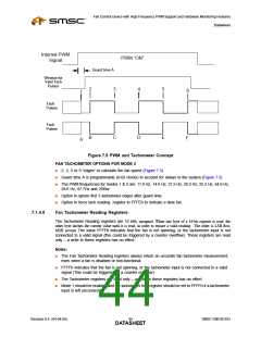
Figure 7.5 PWM and Tachometer Concept
FAN TACHOMETER OPTIONS FOR MODE 2
■
■
■
2, 3, 5 or 9 “edges” to calculate the fan speed (Figure 7.5)
Guard time A is programmable (8-63 clocks) to account for delays in the system (Figure 7.5)
The PWM frequencies for modes 1 & 2 are: 11.0 Hz, 14.6 Hz, 21.9 Hz, 29.3 Hz, 35.2 Hz, 44.0 Hz,
58.6 Hz, 87.7Hz and 25Khz
■
■
Option to ignore first 3 tachometer edges after guard time
Option to force tach reading register to FFFEh to indicate a slow fan.
7.1.4.5
Fan Tachometer Reading Registers:
The Tachometer Reading registers are 16 bits, unsigned. When one byte of a 16-bit register is read, the
other byte latches the current value until it is read, in order to ensure a valid reading. The order is LSB first,
MSB second. The value FFFFh indicates that the fan is not spinning, or the tachometer input is not
connected to a valid signal (this could be triggered by a counter overflow). These registers are read
only – a write to these registers has no effect.
Notes:
■
■
The Fan Tachometer Reading registers always return an accurate fan tachometer measurement,
even when a fan is disabled or non-functional.
FFFFh indicates that the fan is not spinning, or the tachometer input is not connected to a valid
signal (This could be triggered by a counter overflow).
■
■
The Tachometer registers are read only – a write to these registers has no effect.
Mode 1 should be enabled and the tachometer limit register should be set to FFFFh if a tachometer
input is left unconnected.
Revision 0.4 (04-04-05)
SMSC EMC6D103
DATA4S4HEET

 SMSC [ SMSC CORPORATION ]