Fan Control Device with High Frequency PWM Support and Hardware Monitoring Features
Datasheet
Auto Fan Mode
Initiated
End Polling Cycle
No
Begin Polling
Cycle
End Fan Spin Up
Yes
Spin Up
Time Elapsed?
(5C-5E)
Fan Spinning Up?
Yes
Set fan output to
auto fan mode
Set Fan Output to
0%
minimum speed.
No
(63~65)
Override all PWM
Temp >=
AbsLimit
(69~6B)
outputs to 100%
duty cycle except if
disabled or in
Yes
No
manual mode
No
Yes
Temp >=
Hyst Temp
Temp >= Limit
(66~68)
Off/Min set to 1?
(62)
No
No
Set Fan Output to
100%
(6C~6D)
No
Yes
Yes
Yes
Fan Output
At 0%?
Set fan to min
PWM
Fan Output
At 0%?
Begin Fan Spin-Up
Yes
No
Set fan speed based on
Auto Fan Range
Algorithm*
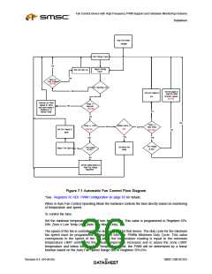
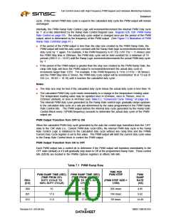
Figure 7.1 Automatic Fan Control Flow Diagram
*See Registers 5C-5Eh: PWM Configuration on page 65 for details.
When in Auto Fan Control Operating Mode the hardware controls the fans directly based on monitoring
of temperature and speed.
To control the fans:
Set the minimum temperature that will turn the fans on. This value is programmed in Registers 67h-
69h: Zone x Low Temp Limit (Auto Fan Mode Only).
The speed of the fan is controlled by the duty cycle set for that device. The duty cycle for the minimum
fan speed must be programmed in Registers 64h-66h: PWMx Minimum Duty Cycle. This value
corresponds to the speed of the fan when the temperature reading is equal to the minimum
temperature LIMIT setting. As the actual temperature increases and is above the Zone LIMIT
temperature and below the Absolute Temperature Limit, the PWM will be determined by a linear
function based on the Auto Fan Speed Range bits in Registers 5Fh-61h.
Revision 0.4 (04-04-05)
SMSC EMC6D103
DATA3S6HEET

 SMSC [ SMSC CORPORATION ]