Fan Control Device with High Frequency PWM Support and Hardware Monitoring Features
Datasheet
Set the absolute temperature for each zone in Registers 6Ah-6Ch: Zone x Temp Absolute Limit (Auto
Fan Mode only). If the actual temperature is equal to or exceeds the absolute temperature in one or
more of the associated zones, all Fans operating in auto mode will be set to Full on, regardless of
which zone they are operating in (except those that are disabled or configured for Manual Mode).
Note: Fans can be disabled via the PWMx Configuration registers and the absolute temperature
safety feature can be disabled by writing 80h into the Zone x Temp Absolute Limit registers.
To set the mode to operate in auto mode, set Bits[7:5] Zone/Mode, located in Registers 5Ch-5Eh: PWM
Configuration Bits[7:5]=’000’ for PWM on Zone 1; Bits[7:5]=’001’ for PWM on Zone 2; Bits[7:5]=’010’
for PWM on Zone 3. If the “Hottest” option is chosen (101 or 110), then the PWM output is controlled
by the zone that results in the highest PWM duty cycle value.
Notes:
■
■
Software can be alerted of an out-of-limit condition by the INT# pin if a status bit is set and enabled
and the interrupt function is enabled on either the PWM2 or TACH3 pins
Software can monitor the operation of the Fans through the Fan Tachometer Reading registers and
by the PWM x Current PWM duty registers. It can also monitor current temperature readings
through the Temperature Limit Registers if hardware monitoring is enabled.
■
Fan control in auto mode is implemented without any input from external processor.
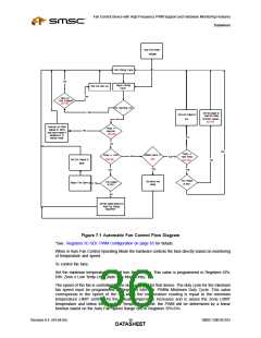
In auto “Zone” mode, the speed is adjusted automatically as shown in the following figure. Fans are
assigned to a zone(s). It is possible to have more than one fan assigned to a thermal zone or to have
multiple zones assigned to one fan.
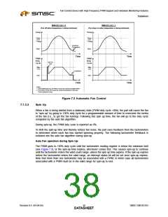
Figure 7.2 on page 38 shows the control for the auto fan algorithm. The part allows a minimum
temperature to be set, below which the fan will run at minimum speed . A temperature range is
specified over which the part will automatically adjust the fan speed. If the fan is off and the current
temperature is below the minimum temperature, then when the temperature exceeds the minimum, the
fan will “spin up” by going on full for a programmable amount of time. Following this spin up time, the
fan will go to a duty cycle computed by the auto fan algorithm. As the temperature rises, the duty cycle
will increase until the fan is running at full-speed when the temperature reaches the minimum plus the
range value. The effect of this is a temperature feedback loop, which will cause the temperature to
reach equilibrium between the minimum temperature and the minimum temperature plus the range.
Provided that the fan has adequate cooling capacity for all environmental and power dissipation
conditions, this system will maintain the temperature within acceptable limits, while allowing the fan to
run slower (and quieter) when less cooling is required.
SMSC EMC6D103
Revision 0.4 (04-04-05)
DATA3S7HEET

 SMSC [ SMSC CORPORATION ]