Fan Control Device with High Frequency PWM Support and Hardware Monitoring Features
Datasheet
It should be noted that the actual duty cycle on the pin is created by the PWM Ramp Rate Control
block and latched on the rising edge of the PWM output. Therefore, the current PWM duty cycle may
lag the PWM Calculated Duty Cycle.
7.1.4
Fan Speed Monitoring
The chip monitors the speed of the fans by utilizing fan tachometer input signals from fans equipped
with tachometer outputs. The fan tachometer inputs are monitored by using the Fan Tachometer
registers. These signals, as well as the Fan Tachometer registers, are described below.
The tachometers will operate in one of two modes:
■
Mode 1: Standard tachometer reading mode. This mode is used when the fan is always powered
when the duty cycle is greater than 00h.
■
Mode 2: Enhanced tachometer reading mode. This mode is used when the PWM is pulsing the fan.
7.1.4.1
7.1.4.2
TACH Inputs
The tachometer inputs are implemented as digital input buffers with logic to filter out small glitches on
the tach signal.
Selecting the Mode of Operation:
The mode is selected through the Mode Select bits located in the Tach Option register. This Mode
Select bit is defined as follows:
■
0=Mode 1: Standard tachometer reading mode
■
1=Mode 2 (default): Enhanced tachometer reading mode.
Default Mode of Operation:
■
■
■
■
■
■
■
■
Mode 2
Slow interrupt disabled (Force FFFEh)
Tach interrupt enabled via enable bit
Tach Limit = FFFFh
Look for 5 tach edges
Don’t ignore first 3 edges after guard time
Guard Time = 32 clock periods (1 clock period = 1/90kHz).
Tach readings updated once a second
7.1.4.3
Mode 1 – Always Monitoring
Mode 1 is the simple case. In this mode, the Fan is always powered when it is ‘ON’ and the fan
tachometer output ALWAYS has a valid output. This mode is typically used if a linear DC Voltage
control circuit drives the fan. In this mode, the fan tachometer simply counts the number of 90kHz
pulses between the programmed number of edges (default = 5 edges). The fan tachometer reading
registers are continuously updated.
Notes:
■
Some enhanced features added to support Mode 2, are available to Mode 1 also. They are:
programmable number of tach edges and force tach reading register to FFFEh to indicate a SLOW
fan.
■
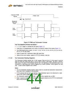
Five edges or two tach pulses are generated per revolution.
The counter is used to determine the period of the Fan Tachometer input pulse. The counter starts
counting on the first edge and continues counting until it detects the last edge or until it reaches FFFFh.
If the programmed number of edges is detected on or before the counter reaches FFFFh, the reading
Revision 0.4 (04-04-05)
SMSC EMC6D103
DATA4S2HEET

 SMSC [ SMSC CORPORATION ]