Fan Control Device with Hardware Monitoring and Acoustic Noise Reduction Features
Datasheet
Description of Ramp Rate Control bits:
If the Remote1 or Remote2 pins are connected to a processor or chipset, instantaneous temperature
spikes may be sampled by the part. The auto fan control logic calculates the PWM duty cycle for all
temperature readings. If Ramp Rate Control is disabled, the PWM output will jump or oscillate
between different PWM duty cycles causing the fan to suddenly change speeds, which creates
unwanted fan noise. If enabled, the PWM Ramp Rate Control logic will prevent the PWM output from
jumping, instead the PWM will ramp up/down towards the new duty cycle at a pre-determined ramp
rate.
Ramp Rate Control
The Ramp Rate Control logic limits the amount of change to the PWM duty cycle over a period of time.
This period of time is programmable via the Ramp Rate Control bits. For a detailed description of the
Ramp Rate Control bits see Table 7.12. For a description of the Ramp Rate Control logic see Ramp
Rate Control Logic on page 34.
Note:
■
■
■
■
RR1E, RR2E, and RR3E enable PWM Ramp Rate Control for PWM 1, 2, and 3 respectively.
RR1-2, RR1-1, and RR1-0 control ramp rate time for PWM 1
RR2-2, RR2-1, and RR2-0 control ramp rate time for PWM 2
RR3-2, RR3-1, and RR3-0 control ramp rate time for PWM 3
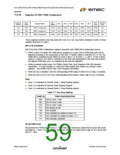
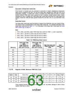
Table 7.12 PWM Ramp Rate Control
PWM RAMP TIME
(SEC)
PWM RAMP TIME
(SEC)
(TIME FROM 33%
DUTY CYCLE TO
100% DUTY CYCLE)
(TIME FROM 0%
DUTY CYCLE TO
100% DUTY CYCLE)
TIME PER PWM STEP
(PWM STEP SIZE =
1/255)
PWM
RAMP RATE
(HZ)
RRX-[2:0]
000
001
010
011
100
101
110
111
35
17.6
11.8
7.0
52.53
26.52
17.595
10.455
6.63
206 msec
104 msec
69 msec
41 msec
26 msec
18 msec
10 msec
5 msec
4.85
9.62
14.49
24.39
38.46
55.56
100
4.4
3.0
4.59
1.6
2.55
0.8
1.275
200
7.2.19
Registers 64-66h: Minimum PWM Duty Cycle
Register
Address
Read/
Write
Bit 7
Bit 0
Default
Value
Register Name
Bit 6
Bit 5
Bit 4
Bit 3
Bit 2
Bit 1
(MSb)
(LSb)
64h
65h
66h
R/W
R/W
R/W
PWM1 Minimum Duty Cycle
PWM2 Minimum Duty Cycle
PWM3 Minimum Duty Cycle
7
7
7
6
6
6
5
5
5
4
4
4
3
3
3
2
2
2
1
1
1
0
0
0
80h
80h
80h
These registers become read only when the Lock bit is set. Any further attempts to write to these
registers shall have no effect.
SMSC EMC6D102
Revision 0.4 (04-05-05)
DATA6S3HEET

 SMSC [ SMSC CORPORATION ]