Fan Control Device with Hardware Monitoring and Acoustic Noise Reduction Features
Datasheet
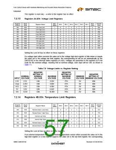
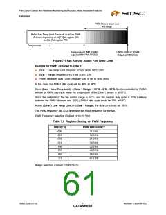
PWM Duty is linear over
this range
Below Fan Temp Limit: Fan is off or at Fan PWM
Minimum depending on bit[7:5] of register 62h
and bit 2 of register 7Fh
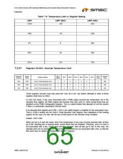
Temperature
Temperature LIMIT: PWM
output at MIN FAN SPEED
LIMIT+ RANGE: PWM
Output at 100% Duty
Figure 7.1 Fan Activity Above Fan Temp Limit
Example for PWM1 assigned to Zone 1:
■
■
■
Zone 1 Low Temp Limit (Register 67h) is set to 50°C (32h).
Zone 1 Range (Register 5Fh) is set to 8°C (7h)
PWM1 Minimum Duty Cycle (Register 64h) is set to 50% (80h)
In this case, the PWM1 duty cycle will be 50% at 50°C.
Since (Zone 1 Low Temp Limit) + (Zone 1 Range) = 50°C + 8°C = 58°C, the fan controlled by PWM1
will run at 100% duty cycle when the temperature of the Zone 1 sensor is at 58°C.
Since the midpoint of the fan control range is 54°C, and the median duty cycle is 75% (Halfway
between the PWM Minimum and 100%), PWM1 duty cycle would be 75% at 54°C.
Above (Zone 1 Low Temp Limit) + (Zone 1 Range), the duty cycle must be 100%.
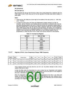
The PWM frequency bits [2:0] determine the PWM frequency for the fan.
PWM Frequency Selection (Default =011=29.3Hz)
Table 7.9 Register Setting vs. PWM Frequency
FREQ[2:0]
PWM FREQUENCY
000
001
010
011
100
101
110
111
11.0 Hz
14.6 Hz
21.9 Hz
29.3 Hz
35.2 Hz
44.0 Hz
58.6 Hz
87.7 Hz
Range Selection (Default =1100=32×C)
SMSC EMC6D102
Revision 0.4 (04-05-05)
DATA6S1HEET

 SMSC [ SMSC CORPORATION ]