Fan Control Device with Hardware Monitoring and Acoustic Noise Reduction Features
Datasheet
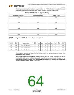
These registers specify the minimum duty cycle that the PWM will output when the measured
temperature reaches the Temperature LIMIT register setting in Auto Fan Control Mode.
Table 7.13 PWM Duty vs. Register Setting
MINIMUM PWM DUTY
VALUE (DECIMAL)
VALUE (HEX)
0%
0
00h
.
.
.
.
.
.
.
.
.
25%
64
40h
.
.
.
.
.
.
.
.
.
50%
128
80h
.
.
.
.
.
.
.
.
.
100%
255
FFh
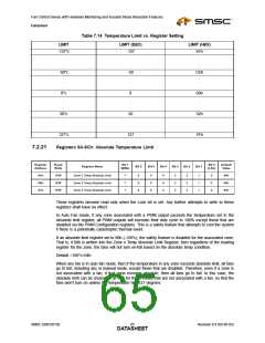
7.2.20
Registers 67-69h: Zone Low Temperature Limit
Register
Address
Read/
Write
Bit 7
Bit 0
Default
Value
Register Name
Bit 6
Bit 5
Bit 4
Bit 3
Bit 2
Bit 1
(MSb)
(LSb)
67h
68h
69h
R/W
R/W
R/W
Zone 1 Low Temp Limit
Zone 2 Low Temp Limit
Zone 3 Low Temp Limit
7
7
7
6
6
6
5
5
5
4
4
4
3
3
3
2
2
2
1
1
1
0
0
0
5Ah
5Ah
5Ah
These registers become read only when the Lock bit is set. Any further attempts to write to these
registers shall have no effect.
These are the temperature limits for the individual zones. When the current temperature equals this
limit, the fan will be turned on if it is not already. When the temperature exceeds this limit, the fan
speed will be increased according to the auto fan algorithm based on the setting in the Zone x Range
/ PWMx Frequency register. Default = 90°C=5Ah
Revision 0.4 (04-05-05)
SMSC EMC6D102
DATA6S4HEET

 SMSC [ SMSC CORPORATION ]