Fan Control Device with Hardware Monitoring and Acoustic Noise Reduction Features
Datasheet
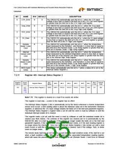
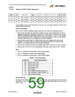
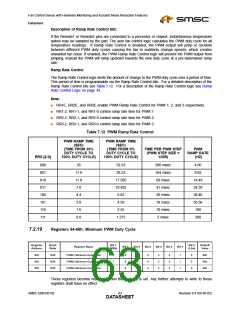
7.2.16
Registers 5C-5Eh: PWM Configuration
Register
Address
Read/
Write
Bit 7
Bit 0
Default
Value
Register Name
Bit 6
Bit 5
Bit 4
Bit 3
Bit 2
Bit 1
(MSb)
(LSb)
5Ch
5Dh
5Eh
R/W
R/W
R/W
PWM 1 Configuration
PWM 2 Configuration
PWM 3 Configuration
ZON2
ZON2
ZON2
ZON1
ZON1
ZON1
ZON0
ZON0
ZON0
INV
INV
INV
RES
RES
RES
SPIN2
SPIN2
SPIN2
SPIN1
SPIN1
SPIN1
SPIN0
SPIN0
SPIN0
62h
62h
62h
These registers become read only when the Lock bit is set. Any further attempts to write to these
registers shall have no effect.
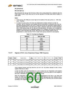
Bits [7:5] Zone/Mode
Bits [7:5] of the PWM Configuration registers associate each PWM with a temperature sensor.
■
When in Auto Fan Mode, the PWM will be assigned to a zone, and its PWM duty cycle will be
adjusted according to the temperature of that zone. If ‘Hottest’ option is selected (101 or 110), the
PWM will be controlled by the hottest of zones 2 and 3, or of zones 1, 2, and 3. If one of these
options is selected, the PWM is controlled by the limits and parameters for the zone that requires
the highest PWM duty cycle, as computed by the auto fan algorithm.
■
When in manual control mode, the PWMx Current Duty Cycle Registers (30h-32h) become
Read/Write. It is then possible to control the PWM outputs with software by writing to these
registers. See PWMx Current Duty Cycle Registers description.
■
■
When the fan is disabled (100) the corresponding PWM output is driven low (or high, if inverted).
When the fan is Full On (011) the corresponding PWM output is driven high (or low, if inverted).
Note:
■
Zone 1 is controlled by Remote Diode 1 Temp Reading register
■
■
Zone 2 is controlled by Internal Temp Reading Register
Zone 3 is controlled by Remote Diode 2 Temp Reading register
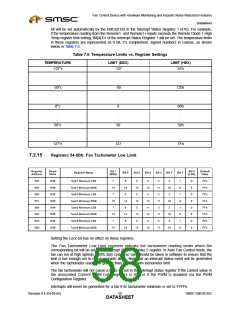
Table 7.7 Fan Zone Setting
ZON[7:5]
PWM CONFIGURATION
Fan on zone 1 auto
Fan on zone 2 auto
Fan on zone 3 auto
Fan always on full
000
001
010
011
100
101
110
111
Fan disabled
Fan controlled by hottest of zones 2,3
Fan controlled by hottest of zones 1,2,3
Fan manually controlled
Bit [4] PWM Invert
Bit [4] inverts the PWM output. If set to 1, 100% duty cycle will yield an output that is low for 255 clocks
and high for 1 clock. If set to 0, 100% duty cycle will yield an output that is high for 255 clocks and
low for 1 clock.
SMSC EMC6D102
Revision 0.4 (04-05-05)
DATA5S9HEET

 SMSC [ SMSC CORPORATION ]