Fan Control Device with Hardware Monitoring and Acoustic Noise Reduction Features
Datasheet
Bit [3] Reserved
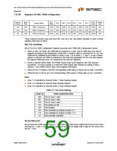
Bits [2:0] Spin Up
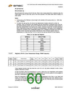
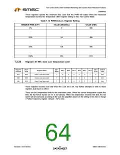
Bits [2:0] specify the ‘spin up’ time for the fan. When a fan is being started from a stationary state, the
PWM output is held at 100% duty cycle for the time specified in the table below before scaling to a
lower speed.
Notes:
■
■
During spin-up, the PWM pin is forced high for the duration of the spin-up time (i.e., 100% duty
cycle = 256/256)
To reduce the spin-up time, this device has implemented a feature referred to as Spin Up
Reduction. Spin Up Reduction uses feedback from the tachometers to determine when each fan
has started spinning properly. Spin up for a PWM will end when the tachometer reading register is
below the minimum limit, or the spin-up time expires, whichever comes first. All tachs associated
with a PWM must be below min. for spin-up to end prematurely. This feature can be disabled by
clearing bit 4 (SUREN) of the Configuration register (7Fh). If disabled, the all fans go on full for the
duration of their associated spin up time. Note that the Tachx minimum registers must be
programmed to a value less than FFFFh in order for the spin-up reduction to work properly.
Table 7.8 Fan Spin-Up Register
SPIN[2:0]
SPIN UP TIME
000
001
010
011
100
101
110
111
0 sec
100ms
250ms (default)
400ms
700ms
1000ms
2000ms
4000ms
7.2.17
Registers 5F-61h: Zone Temperature Range, PWM Frequency
Register
Address
Read/
Bit 7
Bit 0
Default
Value
Register Name
Bit 6
Bit 5
Bit 4
Bit 3
Bit 2
Bit 1
Write
R/W
R/W
R/W
(MSb)
(LSb)
5Fh
60h
61h
Zone 1 Range / Fan 1 Frequency
Zone 2 Range / Fan 2 Frequency
Zone 3 Range / Fan 3 Frequency
RAN3
RAN3
RAN3
RAN2
RAN2
RAN2
RAN1
RAN1
RAN1
RAN0
RAN0
RAN0
RES
RES
RES
FRQ2
FRQ2
FRQ2
FRQ1
FRQ1
FRQ1
FRQ0
FRQ0
FRQ0
C3h
C3h
C3h
These registers become read only when the Lock bit is set. Any further attempts to write to these
registers shall have no effect.
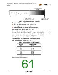
In Auto Fan Mode, when the temperature for a zone is above the Low Temperature Limit (registers
67-69h) and below the Absolute Temperature Limit (registers 6A-6Ch) the speed of a fan assigned to
that zone is determined as follows by the auto fan control logic.
When the temperature reaches the temperature value programmed in the Zone x Low Temp Limit
register, the PWM output assigned to that zone is at PWMx Minimum Duty Cycle. Between Zone x
Low Temp Limit and (Zone x Low Temp Limit + Zone x Range), the PWM duty cycle increases linearly
according to the temperature as shown in the figure below.
Revision 0.4 (04-05-05)
SMSC EMC6D102
DATA6S0HEET

 SMSC [ SMSC CORPORATION ]