Legacy-Free Keyboard/Embedded Controller with SPI and LPC Docking Interface
IBF interrupt bit D7 is set when the host writes to the KBD Data/Command Write register and is cleared
when the 8051 reads from that register.
KBD SCAN [D6]
KBD SCAN interrupt bit D6 is set when any Keyboard Scan In (KSI) pins transition high to low.
EC_IBF [D5]
EC_IBF interrupt bit D5 is set when the host writes to the EC Command or Data port (see "IBF Bit –
D1" in Chapter 4).
EC_OBF [D4]
EC_OBF interrupt bit D4 is asserted when the OBF bit in the EC Status register has been cleared (see
"OBF Bit – D0" in Chapter 4).
GPIO3 [D3]
GPIO3 interrupt bit D3 is set on either positive or negative-going edge of transition of the GPIO3 pin
I2C/SMBus 1 [D2]
When I2C/SMBus 1 bit is equal to 1 an I2C/SMBus IRQ is active.
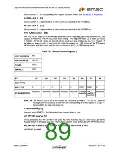
SYS-MBOX [D1]
SYS-MBOX interrupt bit D1 is set when the host writes to mailbox register 0. The bit is cleared when
mailbox register 0 is read (see Section 17.5, "The System/8051 Interface Registers").
ANY WUP [D0]
The ANYWUP interrupt bit D0 is set when any GRP1 on Figure 7.4 wakeup source is asserted. The
bit is cleared bu writting a ‘1’ to this register.
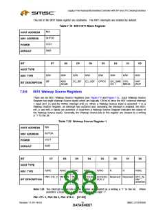
7.9.5
8051 INT1 Mask Register
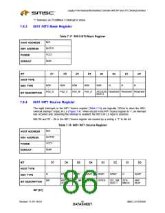
The eight interrupts in the INT1 Source register (Table 7.18) are enabled by bits of the same name in
the INT1 Mask register (Table 7.19).
When any bit in the INT1 Mask register is ‘0’, the interrupt is enabled. When any bit in the INT1 Mask
register is ‘1’, the interrupt is masked. When masked interrupts are asserted, the interrupt will be visible
in the interrupt source register but will not assert an interrupt to the 8051.
SMSC LPC47N350
Revision 1.1 (01-14-03)
DATA6S9HEET

 SMSC [ SMSC CORPORATION ]