Legacy-Free Keyboard/Embedded Controller with SPI and LPC Docking Interface
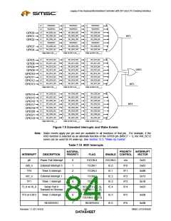
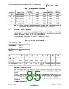
Table 7.15 8051 Interrupts (continued)
NATURAL
PRIORITY
ENABLE CONTROL
INTERRUPT
VECTOR
INTERRUPT
DESCRIPTION
PRIORITY
FLAG
int2
int3_n (1)
int4
External Interrupt 2
External Interrupt 3
External Interrupt 4
External Interrupt 5
RESERVED
8
EXIF.4
EXIF.5
EIE.0
EIE.1
EIE.2
EIE.3
EIE.4
EIP.0
EIP.1
EIP.2
EIP.3
EIP.4
0x43
0x4B
0x53
0x5B
0x63
9
10
11
12
EXIF.6
int5_n
EXIF.7
EICON.3
Note 7.24 The int5_n interrupt is used to restart the 8051 from sleep mode. This interrupt includes the
interrupt WAKE UP sources from GRP1 and Grp2 on Figure 7.4 and Figure 7.5.
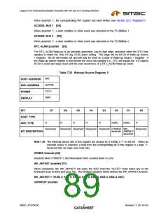
7.9.2
8051 INT0 Source Register
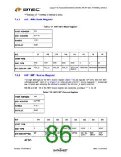
The five interrupts in the INT0 Source register (Table 7.16) are logically OR’ed to drive the 8051 int0_n
interrupt (Figure 7.4). When any bit in the INT0 Source register is ‘1’, an interrupt has occurred and,
assuming the interrupt is enabled, the 8051 int0_n input is asserted.
The bits in the INT0 Source register are cleared by a writing a “1” to the bit.
Table 7.16 8051 Int0 Source Register
N/A
HOST ADDRESS
8051 ADDRESS
POWER
0x7F00
VCC1
0x00
DEFAULT
BIT
D7
D6
D5
D4
D3
D2
D1
D0
-
-
-
-
-
-
-
-
HOST TYPE
8051 TYPE
R/WC
R/WC
R/WC
R/WC
R/WC
R
R
R
PS2_D
PS2_C
PS2_B
PS2_A
I2C_SM Reserved Reserved Reserved
BUS 2
BIT DESCRIPTION
SMSC PS/2 A:D Interrupts – D[7:4]
INT0 Source register bit D7 is the SMSC PS/2 Channel D interrupt, bit D6 is the SMSC PS/2 Channel
C interrupt, bit D5 is the SMSC PS/2 Channel B interrupt, and bit D4 is the SMSC PS/2 Channel A
interrupt.
The PS2_D interrupt is associated with the PS2CLK and PS2DAT alternate functions of the GPIO20
and GPIO21 pins. The PS2_C is associated with the IMCLK and IMDATA pins. The PS2_B interrupt is
associated with the KCLK and KDAT pins. The PS2_A is associated with the EMCLK and EMDATA pins.
Note that when a start bit is detected in receive mode for a channel, an interrupt is also generated for
that channel.
I2C/SMBus 2 Interrupt – D3
SMSC LPC47N350
Revision 1.1 (01-14-03)
DATA6S7HEET

 SMSC [ SMSC CORPORATION ]