Legacy-Free Keyboard/Embedded Controller with SPI and LPC Docking Interface
“1” Indicates an I2C/SMBus 2 interrupt is active.
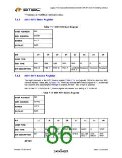
7.9.3
8051 INT0 Mask Register
Table 7.17 8051 INT0 Mask Register
N/A
HOST ADDRESS
8051 ADDRESS
POWER
0x7F01
VCC1
0x00
DEFAULT
BIT
D7
D6
D5
D4
D3
D2
D1
D0
-
-
-
-
-
-
-
-
HOST TYPE
8051 TYPE
R/W
R/W
R/W
R/W
R/W
R
R
R
PS2_D
PS2_C
PS2_B/
PS2_A
ACCESS Reserved Reserved Reserved
BUS 2
BIT DESCRIPTION
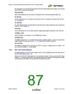
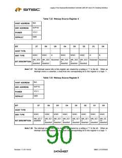
7.9.4
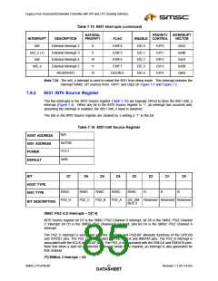
8051 INT1 Source Register
The eight interrupts in the INT1 Source register (Table 7.18) are logically ‘OR’ed to drive the 8051
external interrupt 1 input, int1_n (Figure 7.4). When any bit in the INT1 Source register is ‘1’, an interrupt
has occurred and, assuming the interrupt is enabled, the 8051 int1_n input is asserted.
Bits D0 and D2 – D6 in the INT1 Source register are cleared by a writing a “1” to the bit.
Table 7.18 8051 INT1 Source Register
N/A
HOST ADDRESS
8051 ADDRESS
POWER
0x7F02
VCC1
0x00
DEFAULT
BIT
D7
D6
D5
D4
D3
D2
D1
D0
-
-
-
-
-
-
-
-
HOST TYPE
8051 TYPE
R
R/WC
R/WC
R/WC
R/WC
R/WC
R
R/WC
IBF
KBD
EC_IBF
EC_OBF GPIO3
I2C_SM SYS-
BUS 1 MBOX
ANY
BIT DESCRIPTION
IBF [D7]
SCAN
WUP
Revision 1.1 (01-14-03)
SMSC LPC47N350
DATA6S8HEET

 SMSC [ SMSC CORPORATION ]