Legacy-Free Keyboard/Embedded Controller with SPI and LPC Docking Interface
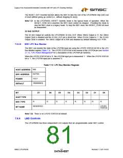
Table 7.14 LED Register
N/A
HOST ADDRESS
8051 ADDRESS
POWER
0x7F21
VCC1
0x00
DEFAULT
BIT
D7
D6
D5
D4
N/A
D3
D2
D1
D0
0
0
0
0
0
0
0
DEFAULT
8051 ACCESS
R
R/W
R/W
R
R/W
R/W
R/W
R/W
Reserved
FDD_
LED1
FDD_
LED0
status
of
PWR_
LED1
PWR_
LED0
BAT_
LED1
BAT_
LED0
BIT DEF
MODE
pin
See
00 FDD LED is off
01 LED flash;
P=1.0 sec
00 PWR LED is off 00 Battery LED is
Note 7.23
01 LED flash;
P=3.0 sec
off
01 LED flash;
P=1.0 sec
10 LED flash;
P=0.5 sec
10 LED flash;
P=1.5 sec
10 LED flash;
P=0.5 sec
11 LED is fully on
11 LED is fully on
11 LED is fully on
Note 7.23 See Section 27.2, "Configuration Register Access," on page 277.
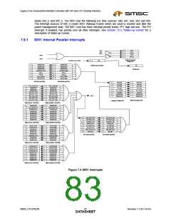
LED on time is T=125msec; “0” is on, “1” is off. Period “P” is indicated above.
P
T
Figure 7.3 LED Output
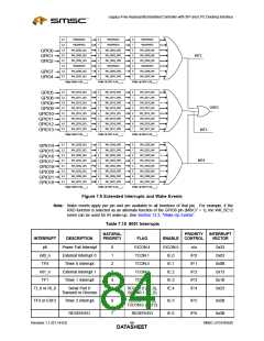
7.9
8051 Interrupts
The eleven 8051 core interrupts are shown described in Table 7.15, "8051 Interrupts". See Appendix B,
"High-Performance 8051 Extended Interrupt Unit," on page 315 for a desciption of the High Performance
8051 Extended Interrupt Unit.
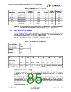
The fanout of Interrupts and Wakeup Evnets are illustrated in Figure 7.4 and Figure 7.5. The active high
Int3 and Int5 outputs from the Extended IRQs shown in Figure 8.4 are inverted into active low 8051 core
Revision 1.1 (01-14-03)
SMSC LPC47N350
DATA6S4HEET

 SMSC [ SMSC CORPORATION ]