Legacy-Free Keyboard/Embedded Controller with SPI and LPC Docking Interface
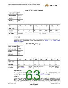
Table 7.2 STOP_COUNT Register
N/A
HOST ADDRESS
8051 ADDRESS
POWER
0x7F2F
VCC1
0x00
DEFAULT
BIT
D7
D6
D5
D4
D3
D2
D1
D0
-
-
-
-
-
-
-
-
HOST TYPE
8051 R/W
BIT NAME
R
R
R
R
R/W
R/W
R/W
R/W
Reserved
STP_CNT[3:0]
STP_CNT[x]
This defines the number of machine cycles from when the internal IRESET_OUT bit is cleared until the
external nRESET_OUT pin goes inactive high (deasserts). See Section 7.8.3.5, "Output Enable
Register," on page 62
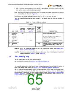
Table 7.3 KSTP_CLK Register
N/A
HOST ADDRESS
8051 ADDRESS
POWER
0x7F27
VCC1
0x10
DEFAULT
BIT
D7
D6
D5
D4
D3
D2
D1
D0
-
-
-
-
-
-
-
-
HOST TYPE
8051 R/W
R/W
R/W
R/W
R/W
R
R
R/W
R/W
KBDCLK[1:0]
KBCLK/
ROSC
ROSCEN Reserved
PLL_STOP KBDCLK
ENABLE
BIT NAME
(See Table 7.4)
KBDCLK/ENABLE
When the KBDCLK ENABLE bit is “0”, the 8051 PLL clock is stopped. When KBDCLK ENABLE is “1”,
the 8051 PLL clock is running (See Table 7.4, "KBDCLK Control Bit Encoding").
PLL_STOP
The PLL_STOP bit D1 is used to control the power state of the 14.318MHz PLL. When the PLL_STOP
bit is “1,” the PLL and all of the internal clocks except for the RTC and Ring Oscillator are stopped.
When the PLL_STOP bit is “0,” the PLL and all of the internal clocks are running. When VCC2 is active
SMSC LPC47N350
Revision 1.1 (01-14-03)
DATA4S5HEET

 SMSC [ SMSC CORPORATION ]