Legacy-Free Keyboard/Embedded Controller with SPI and LPC Docking Interface
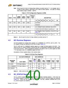
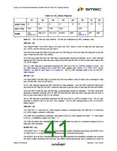
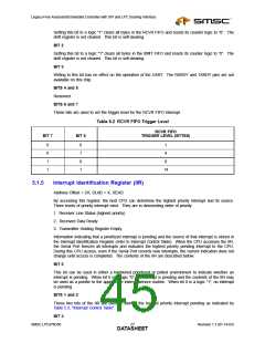
Table 4.3 EC_Status Register
D7
D6
D5
D4
D3
D2
D1
D0
R
R
R
R
R
R
R
R
HOST TYPE
8051 TYPE
R/W
R/W
R/W
R/W
R/W
UD
SMI_EVT
SCI_EVT
BURST
CMD
UD
IBF
OBF
NAME
(Note 4.3)
(Note 4.3)
Note 4.3 The UD bits are User-Defined. UD bits are maintained by 8051 software, only.
OBF Bit – D0
The Output Buffer Full (OBF) flag is set when the 8051 writes a byte of data into the data port
(EC_DATA), but the host has not yet read it.
Once the host reads the status byte and sees the OBF flag set, the host reads the data port to get the
byte of data that the 8051 has written.
Once the host reads the data, the OBF flag is automatically cleared by hardware. An EC_OBF interrupt
signals the 8051 that the data has been read by the host and the 8051 is free to write more data to the
EC_DATA register.
The EC_OBF interrupt is generated whenever the OBF bit in the EC_STATUS register is reset. The
EC_OBF interrupt is routed to bit 4 in the INT1 SRC register (see Section 7.9.4, "8051 INT1 Source
Register," on page 68 and Figure 7.4 on page 65). The EC_OBF interrupt mask is bit 4 in the INT1
Mask register.
IBF Bit – D1
The Input Buffer Full (IBF) flag is set when the host has written a byte of data to the command or data
port, but the 8051 has not yet read it.
An EC_IBF interrupt signals the 8051 that there is data available. Once the 8051 reads the status byte
and sees the IBF flag set, the 8051 reads the data port to get the byte of data that the host has written.
Once the 8051 reads the data, the IBF flag is automatically cleared by hardware. The 8051 must then
generate a software interrupt (SCI) to alert the host that the data has been read and that the host is
free to write more data to the ECI as needed.
An EC_IBF interrupt is generated whenever the IBF bit in the EC_STATUS register is set. The EC_IBF
interrupt is routed to bit 5 in the INT1 SRC register. The EC_IBF interrupt mask is bit 5 in the INT1
Mask register.
CMD Bit – D3
The CMD bit is “1” when the EC_DATA register contains a command byte; the CMD bit is “0” when the
EC_DATA register contains a data byte.
The CMD bit is controlled by hardware: host writes to the EC_DATA register set CMD = “0”; host writes
to the EC_COMMAND register set CMD = “1”.
The CMD bit allows the embedded controller to differentiate the start of a command sequence from a
data byte write operation.
BURST Bit – D4
The BURST bit is “1” when the EC is in Burst Mode for polled command processing; the BURST bit is
“0” when the EC is in Normal Mode for interrupt-driven command processing.
The BURST bit is an 8051-maintained software flag that indicates the embedded controller has received
the Burst Enable command from the host, has halted normal processing, and is waiting for a series of
SMSC LPC47N350
Revision 1.1 (01-14-03)
DATA2S3HEET

 SMSC [ SMSC CORPORATION ]