Legacy-Free Keyboard/Embedded Controller with SPI and LPC Docking Interface
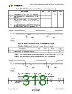
Note 29.7 8051 firmware responds to interrupt and latches data line before rising edge of PS2_CLK
line.
Note 29.8 8051 firmware clears Interrupt by reading the 8051 INT0 Source Register.
29.8
Serial Peripheral Interface (SPI) Timings
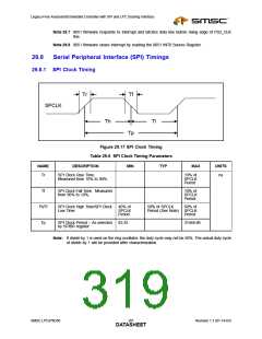
29.8.1 SPI Clock Timing
Tr
Tf
SPCLK
Th
Tl
Tp
Figure 29.17 SPI Clock Timing
Table 29.6 SPI Clock Timing Parameters
NAME
DESCRIPTION
MIN
TYP
MAX
UNITS
Tr
SPI Clock Rise Time.
10% of
ns
Measured from 10% to 90%.
SPCLK
Period
Tf
Th/Tl
Tp
SPI Clock Fall Time. Measured
from 90% to 10%.
10% of
SPCLK
Period
SPI Clock High Time/SPI Clock
Low Time
40% of
50% of SPCLK
60% of
SPCLK
Period
Period (See Note) SPCLK
Period
SPI Clock Period – As selected
by SPIBR register.
83.33
31948.88
Note: If divide by 1 is used on the ring oscillator, the duty cycle may not be 50%. The actual duty cycle
of divide by 1 will be provided after characterization.
SMSC LPC47N350
301
Revision 1.1 (01-14-03)
DATASHEET

 SMSC [ SMSC CORPORATION ]