Legacy-Free Keyboard/Embedded Controller with SPI and LPC Docking Interface
The update cycle also compares each alarm register with the corresponding time register and issues an
alarm if a match or if a "don't care" code is present.
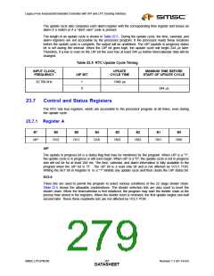
The length of an update cycle is shown in Table 23.5. During the update cycle, the time, calendar, and
alarm registers are not accessible by the processor program. If the processor reads these locations
before the update cycle is complete, the output will be undefined. The UIP (update in progress) status
bit is set during the interval. When the UIP bit goes high, the update cycle will begin 244 µs later.
Therefore, if a low is read on the UIP bit the user has at least 244 µs before time/calendar data will be
changed.
Table 23.5 RTC Update Cycle Timing
INPUT CLOCK
FREQUENCY
UPDATE
MINIMUM TIME BEFORE
UIP BIT
CYCLE TIME
START OF UPDATE CYCLE
32.768 kHz
1
0
1948 µs
-
-
244 µs
23.7
Control and Status Registers
The RTC has four registers, which are accessible to the processor program at all times, even during
the update cycle.
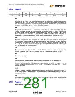
23.7.1 Register A
B7
B6
B5
B4
B3
B2
B1
B0
UIP
DV2
DV1
DV0
RS3
RS2
RS1
RS0
UIP
The update in progress bit is a status flag that may be monitored by the program. When UIP is a "1",
the update cycle is in progress or will soon begin. When UIP is a "0", the update cycle is not in progress
and will not be for at least 244 ms. The time, calendar, and alarm information is fully available to the
program when the UIP bit is “0”. The UIP bit is a read only bit and is not affected by VCC1 POR.
Writing the SET bit in Register B to a "1" inhibits any update cycle and then clears the UIP status bit.
DV2-0
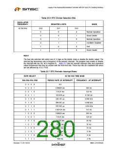
Three bits are used to permit the program to select various conditions of the 22 stage divider chain.
Table 23.6 shows the allowable combinations. The divider selection bits are also used to reset the
divider chain. When the time/calendar is first initialized, the program may start the divider chain at the
precise time stored in the registers. When the divider reset is removed, the first update begins one-half
second later. These three read/write bits are not affected by VCC1 POR.
SMSC LPC47N350
261
Revision 1.1 (01-14-03)
DATASHEET

 SMSC [ SMSC CORPORATION ]