Legacy-Free Keyboard/Embedded Controller with SPI and LPC Docking Interface
22.3
ACPI PM1 Block Base Address
Logical Device 1 in the LPC47N350 configuration space supports the ACPI PM1 Block registers
interface. Three device configuration registers in LDN1 provide activation control and the base address
programming for the ACPI PM1 Block registers (Table 22.1).
Register 0x30 is the Activate register. The activation control (LDN1:CR30.0) qualifies address decoding
for the ACPI PM1 Block registers; e.g., if the Activate bit D0 in the Activate register is “0”, the PM1 Block
addresses will not be decoded; if the Activate bit is “1”, PM1 Block addresses will be decoded depending
on the values programmed in the ACPI PM1 Block Primary Base Address registers.
Registers 0x60 and 0x61 are the ACPI PM1 Block Primary Base Address registers. Register 0x60 is
the ACPI PM1 Block Primary Base Address High Byte, register 0x61 is the ACPI PM1 Block Primary
Base Address Low Byte.
Note: The ACPI PM1 Block base address must be located on eight -byte boundaries; i.e., bits D0 –
D2 in the ACPI PM1 Block Primary Base Address Low Byte must be “0”. Valid ACPI PM1 Block
base address values are 0x0000 – 0x0FF8.
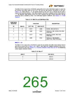
Table 22.1 ACPI PM1 Block Configuration Registers (LDN1)
VCC1&
HARD
SOFT
VCC2
POR
VCC0
POR
INDEX TYPE
RESET
RESET
DESCRIPTION
D7 D6 D5 D4 D3 D2
Activate
RESERVED
D1
D0
0x30
0x60
0x61
R/W
R/W
R/W
0x00
0x00
0x00
0x00
0x00
0x00
0x00
0x00
0x00
-
-
-
Activate
ACPI PM1 Block Primary Base Address High Byte
“0” “0” “0” “0” A11 A10 A9 A8
ACPI PM1 Block Primary Base Address Low Byte
A7 A6 A5 A4 A3 “0” “0” “0”
22.4
ACPI PM1 Block
Description
The ACPI register model consists of a number of fixed register blocks that perform designated functions.
A register block consists of a number of registers that perform Status, Enable and Control functions. The
ACPI specification deals with events (which have an associated interrupt status and enable bits, and
sometimes an associated control function) and control features. The status registers illustrate what
defined function is requesting ACPI interrupt services (SCI). Any status bit in the ACPI specification has
the following attributes:
■
Status bits are only set through some defined hardware or 8051 event.
■
Unless otherwise noted, status bits are cleared by the system writing a “1” to that bit position, and
upon VCC1 POR. Writing a ‘0’ has no effect.
■
■
Status bits only generate interrupts while their associated bit in the enable register is set.
Function bit positions in the status register have the same bit position in the enable register (there
are exceptions to this rule, special status bits have no enables).
■
Note that this implies that if the respective enable bit is reset and the hardware event occurs, the
respective status bit is set; however no interrupt is generated until the enable bit is set. This allows
software to test the state of the event (by examining the status bit) without necessarily generating
an interrupt. There are a special class of status bits that have no respective enable bit, these are
Revision 1.1 (01-14-03)
250
SMSC LPC47N350
DATASHEET

 SMSC [ SMSC CORPORATION ]