Legacy-Free Keyboard/Embedded Controller with SPI and LPC Docking Interface
Table 22.8 Power Management 1 Control Register 2 (continued)
BIT
NAME
SLP_EN
DESCRIPTION
5
This bit is R/W by the Host; reads by the Host always return ‘0’. This bit can be
set (written as ‘1’) but not cleared by the Host (writing ‘0’ has no effect). This bit
is R/W by the 8051, and reads by the 8051 return the true value of the bit. When
set by the Host, this bit is cleared by the 8051 writing a ‘1’ to it; writing ‘0’ has
no effect.
6-7
RESERVED
Reserved bits cannot be written and return “0” when read.
22.6
nEC_SCI PIN INTERFACE
The nEC_SCI pin logic hardware is shown in Figure 22.1.
Any or all of the PWRBTN_STS, SLPBTN_STS, and RTC_STS bits in the PM1_STS 2 register can
assert the nEC_SCI pin if enabled by the PWRBTN_EN, SLPBTN_EN, and RTC_EN bits in the
PM1_EN 2 register. See descriptions of these registers, above.
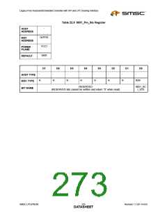
The 8051_SCI_STS bit can assert the nEC_SCI pin at any time, without being enabled. The
8051_SCI_STS bit is located in the 8051_PM_STS register at MMCR address 0x7F83h (Table 22.9).
The 8051_SCI_STS bit is in the LPC47N350 and is read/write by the 8051. If the 8051_SCI_STS bit
is “1”, an interrupt is generated on the nEC_SCI pin.
PM1_STS 2 PM1_EN 2
Register
Register
PWRBTN_STS
SLPBTN_STS
RTC_STS
nEC_SCI
8051_PM_STS Register
8051_SCI_STS
Figure 22.1 Hardware nEC_SCI Interface
Revision 1.1 (01-14-03)
254
SMSC LPC47N350
DATASHEET

 SMSC [ SMSC CORPORATION ]