Legacy-Free Keyboard/Embedded Controller with SPI and LPC Docking Interface
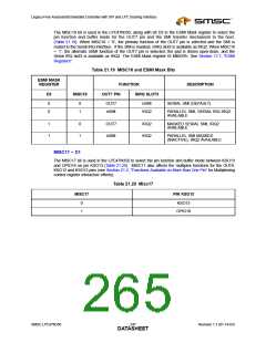
Table 21.15 Misc23 Bit
DESCRIPTION
MISC23
0
1
GPIO15 Function Selected (DEFAULT)
FAN_TACH1 Function Selected
MISC22 – D6
The MISC22 bit is used to select between GPIO7 and PWM3 functions (Table 21.16).
Table 21.16 Misc22 Bit
MISC22
DESCRIPTION
0 (DEFAULT)
1
GPIO7
PWM3
MISC21 – D5
The MISC21 bit is used to select the pin function and the buffer mode between GPIO16 and
FAN_TACH2 for the GPIO16 pin (Table 21.17).
Table 21.17 Misc21 Bit
MISC21
DESCRIPTION
0
1
GPIO16 Function Selected (DEFAULT)
FAN_TACH2 Function Selected
MISC[20:19] D4 – D3
The MISC20 and MISC19 bits are used to select the pin function and the buffer mode between the
2
switched I C/SMBus 2 interface and the GPIO11, GPIO12, GPIO13 and GPIO14 pins. The MISC20 and
2
MISC19 bits control the number of pins allocated for I C/SMBus 2 interface alternate functions as
2
2
2
follows: I C/SMBus 2 interface (4 pins), unswitched I C/SMBus 2 interface (2 pins), or no I C/SMBus
2
2 interface (0 pins). Pins not allocated to the I C/SMBus 2 interface are allocated to GPIO interface.
Table 21.18 Misc[20:19] Bits
MISC19
MISC20
PIN GPIO11
PIN GPIO12
PIN GPIO13
PIN GPIO14
DESCRIPTION
0
0
GPIO11
GPIO12
GPIO13
GPIO14
Four GPIO pins
(Default)
0
1
AB2A_DATA
AB2A_DATA
AB2A_CLK
AB2A_CLK
GPIO13
GPIO14
Switched
2
I C/SMBus 2 and
Two GPIO pins
Switched
1
1
0
1
AB2B_DATA
AB2B_CLK
2
I C/SMBus 2
Reserved
Note 21.2 The function of the GPIO[11:14] pin is RESERVED when MISC[20:19] = 1,1 (Table 21.18).
MISC18 – D2
Revision 1.1 (01-14-03)
246
SMSC LPC47N350
DATASHEET

 SMSC [ SMSC CORPORATION ]