Legacy-Free Keyboard/Embedded Controller with SPI and LPC Docking Interface
Table 13.13 GATEA20 Command/Data Sequence Examples (continued)
SA2
R/W
D[0:7]
IBF FLAG
GATEA20
COMMENTS
1
1
0
1
W
W
W
W
D1
D1
DF
FF
0
0
0
0
Q
Q
1
GATEA20 Turn-on Sequence(*)
1
1
1
0
1
W
W
W
W
D1
D1
DD
FF
0
0
0
0
Q
Q
0
GATEA20 Turn-off Sequence(*)
Invalid Sequence
0
1
1
1
W
W
W
D1
XX**
FF
0
1
1
Q
Q
Q
Notes:
■
■
■
■
All examples assume that the SAEN configuration bit is 0.
"Q" indicates the bit remains set at the previous state.
*Not a standard sequence.
**XX = Anything except D1.
If multiple data bytes, set IBF and wait at state 0. Let the software know something unusual happened.
For data bytes SA2=0, only D[1] is used; all other bits are don't care.
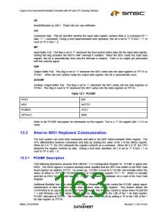
13.4.1 8051 GATEA20 Control Registers
Table 13.14 GATEA20
N/A
HOST
8051
0x7FFB
VCC1
0x01
POWER
DEFAULT
Refer to the GATEA20 Hardware Speed-up description for information on this register. This is a one bit
register (Bits 1-7=0 on read)
Table 13.15 SETGA20L
HOST
N/A
8051
0x7FFE (W)
VCC1
N/A
POWER
DEFAULT
Refer to the GATEA20 Hardware Speed-up description for information on this register. A write to this
register sets GateA20.
Revision 1.1 (01-14-03)
148
SMSC LPC47N350
DATASHEET

 SMSC [ SMSC CORPORATION ]