Legacy-Free Keyboard/Embedded Controller with SPI and LPC Docking Interface
Table 13.16 RSTGA20L
HOST
N/A
8051
0x7FFF (W)
VCC1
N/A
POWER
DEFAULT
Refer to the GATEA20 Hardware Speed-up description for information on this register. A write to this
register resets GateA20.
GateA20 Logic
nIOW_DLY
SAEN
64&nAEN
nIOW_DLY
DD1
To KRESET Gen
nIOW
nIOW
nIOW
SD[7:0] = D1
IBF
D
Q
Address
Data
IBF Bit
DFF
DFE
SD[7:0] = FF
SD[7:0] = FE
nAEN&60
CPU_RESET
A20
0
GATEA20
MUX
1
SETGA20L Reg
Any Write
DD1
D
After D1
SD[1]
Fast_GateA20
Q
S
SAEN
bit-1 of
D
Q
Config Reg 0
nIOW
nAEN&64
R
GATEA20 Reg
R
d0
Write
Read
bit-0
bit-0
RSTGA20L Reg
nIOW
nAEN&60
D
Any Write
Trailing Edge Delay
ENAB_P92
GATEA20 Reg
d0
Port92 Reg
ALT_A20
Bit 1
Delay
VCC
nIOW_DLY
nIOW
24MHz
Q
Q
D
D
D
nQ
R
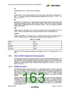
Figure 13.1 GATEA20 Implementation Diagram
13.4.2 CPU_RESET Hardware Speed-Up
The ALT_CPU_RESET bit generates, under program control, the nALT_RST signal, which provides an
alternate, means to drive the LPC47N350 CPU_RESET pin which in turn is used to reset the Host CPU.
The nALT_RST signal is internally NANDed together with the nKBDRESET pulse from the KRESET
Speed up logic to provide an alternate software means of resetting the host CPU. Note: before another
nALT_RST pulse can be generated, ALT_CPU_RESET must be cleared to “0” either by a system reset
(nRESET_OUT asserted) or by a write to the Port92 register with bit 0 = “0”. A nALT_RST pulse is not
generated in the event that the ALT_CPU_RESET bit is cleared and set before the prior nALT_RESET
pulse has completed.
SMSC LPC47N350
149
Revision 1.1 (01-14-03)
DATASHEET

 SMSC [ SMSC CORPORATION ]