SiI 1161 PanelLink Receiver
Data Sheet
Receiver Layout
The receiver chip should be placed as close as possible to the input connector that carries the TMDS signals.
For a system using the industry-standard DVI connector (see http://www.ddwg.org), the differential lines should
be routed as directly as possible from connector to receiver. Differential pair length is not critical but ideally
should be less than 10cm.
PanelLink devices are tolerant of skews between differential pairs, so spiral skew compensation for path length
differences is not required. However, each conductor of the differential pair should be routed together with equal
trace lengths. Vias should be avoided, but if used they should be placed on both signal lines of the differential
pair in a way that gives both lines equivalent reflection characteristics. Figure 28 illustrates acceptable routing
practices for TMDS signals from a DVI connector, while Figure 29 shows an example of actual trace routing.
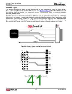
<10cm
Figure 28. General Signal Routing Recommendations
RX2+
RX2-
RX1+
RX1-
RX0+
RX0-
RXC+
RXC-
Figure 29. Signal Trace Routing Example
37
SiI-DS-0096-D

 SILICONIMAGE [ Silicon image ]