SiI 1160 PanelLink Transmitter
Data Sheet
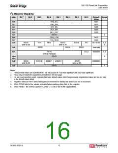
I2C Register Mapping
Addr.
Bit 7
Bit 6
Bit 5
Bit 4
Bit 3
Bit 2
Bit 1
Bit 0
Default
Value
Notes
VND_IDL
0x01
0x00
0x06
0x00
0x00
0x0
0x1
0x2
0x3
0x4
0x5
0x6
0x7
0x8
VND_IDH
DEV_IDL
DEV_IDH
DEV_REV
RSVD
4
FRQ_LOW
FRQ_HIGH
0x19
0x64
RSVD
write to 00
VEN
HEN
RSVD
write to 01
RSEN
EDGE
PD
00110100
3, 5,
6
RSVD
RSVD
read only
10000001
0x9
0xA
RSVD
CTL0
5, 6
4
write to 1000000
RSVD
0xB-
0xD
RSVD
EZONE
ZONEF
ZONEO
RSVD
00000001
0xE
write to 00
write to 001
RSVD
4
0xF
Notes:
1. Hexadecimal values use a prefix of ‘0x’. All values use bit 7 as most significant, bit 0 as least significant.
2. Read-only or read/write capabilities are noted on the next page.
3. On any reset assertion event, registers that have default values lose their previously programmed value and are set back
to the default values listed.
4. Registers listed as RSVD and shaded gray are reserved for factory use and should not be accessed.
5. Write RSVD bits to the values indicated when writing other bits in the register.
6. Write PD to 1 for normal operation; write CTL0 to 0 for HDMI applications.
SiI-DS-0126-B
12

 SILICONIMAGE [ Silicon image ]