SiI 1160 PanelLink Transmitter
Data Sheet
Power Management Pins
Pin Name
Pin #
Type
Description
PD
26
In
Power Down (active LOW). A HIGH level indicates normal operation. A LOW level
indicates power down mode. During power down mode, all data (DIE/DIO[23:0]), data
enable (DE), clock (IDCK) and control signals (HSYNC, VSYNC, CTL[3:1]), input buffers
are disabled, all output buffers are tri-stated and all internal circuitry is powered down.
When the I2C interface is enabled (ISEL/RST=LOW), this pin is ignored and the PD
register bit is used instead. Tie this pin low if not used.
Differential Signal Data Pins
Pin Name
TX0+
Pin #
40
Type
Description
Analog TMDS Low Voltage Differential Signal input data pairs.
TX0-
39
Analog
TX1+
43
Analog These pins are tri-stated when PD is asserted.
TX1-
42
Analog
TX2+
46
Analog
TX2-
45
Analog
TXC+
35
Analog TMDS Low Voltage Differential Signal input clock pair.
Analog These pins are tri-stated when PD is asserted.
TXC-
34
EXT_SWING
32
Analog Voltage Swing Adjust. A resistor should tie this pin to AVCC. This resistor determines
the amplitude of the voltage swing. A smaller resistor value sets a larger voltage swing
and vice versa. For remote display applications with source termination, a 510Ω resistor
is recommended (see page 24). Without the source termination, use a 560Ω resistor.
Local Control (I2C) Interface
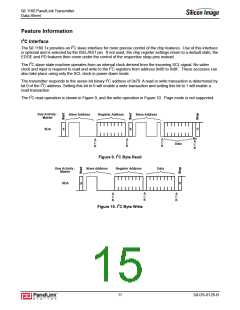
The transmitter can operate with or without an I2C interface connection. Refer to the Feature Information section
for details on using the I2C registers.
Pin Name
ISEL/RST
Pin # Type Description
87
In
I2C Interface Select. If LOW, then the I2C interface is active. If HIGH, the interface is
inactive and chip configuration is taken from strap and default settings. This pin also acts
as an asynchronous reset to the I2C interface controller. Switching this input from HIGH to
LOW after a minimum TRESET high time resets the I2C logic.
MSEN
21
Out
Monitor Sense. The behavior of this output depends on whether the I2C interface is
enabled or disabled.
No I2C (ISEL = HIGH)
MSEN=HIGH: a powered on receiver is detected at the TMDS outputs.
MSEN=LOW: a powered on receiver is not detected.
This Receiver Sense function can only be used in DC-coupled systems.
I2C enabled (ISEL = LOW)
The output is programmable through the I2C interface and can indicate the Hot
Plug or Receiver Sense signal state, or can instead generate a status change interrupt for
those signals.
This pin is an open collector output. An external pull-up resistor (5KΩ recommended) is
required on this pin if the MSEN signal will be used. Otherwise the signal should be tied
low.
SCL
SDA
20
23
In
I2C Clock. When the I2C interface is enabled (ISEL=LOW), this pin acts as the I2C clock
input. This pin is an open collector output. It must be pulled high to VCC through a
resistor; a value of 2.2KΩ is recommended for I2C applications, 2-5KΩ otherwise. This pin
is not 5V-tolerant.
In/Out I2C Data. When the I2C interface is enabled (ISEL=LOW), this pin acts as the I2C data
input and output. This pin is an open collector output. It must be pulled high to VCC
through a resistor; a value of 2.2KΩ is recommended for I2C applications, 2-5KΩ
otherwise. This pin is not 5V-tolerant.
9
SiI-DS-0126-B

 SILICONIMAGE [ Silicon image ]