SiI 1160 PanelLink Transmitter
Data Sheet
Automatic Zone Control
For applications that are not able to program the I2C registers, the chip incorporates an automatic zone control
circuit. This circuit determines whether the input pixel clock is operating in the low frequency range or the high
frequency range, and sets the PLL zone selection accordingly. The chip defaults to the automatic mode of zone
selection after reset.
The zone determination depends primarily on input frequency, but is also affected by operating voltage and chip
temperature. Therefore, it is possible for an automatic zone switch to occur while video input is stable, causing
momentary (~1µs) unevenness in the video output clock and data streams. This could occur, for example, while
the chip is still warming up to its normal operating temperature. However, the automatic selection circuit provides
wide hysteresis to ensure that there will not be any oscillation around the zone switch point.
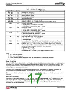
Table 2. Dual Zone PLL I2C Control Register Bits
Register Name
ZONEF
Access
RW
Description
Zone Force. Enable external selection of main PLL operating zone. When ZONEF=1, the
main PLL zone is selected by EZONE.
0 – Automatic zone selection – EZONE bit disabled (default)
1 – Manual zone selection – EZONE bit enabled
RW
RO
External Zone Select. Selects operating zone of main PLL, but only when ZONEF=1
(disabled by default).
EZONE
ZONEO
0 – Low zone (recommended for 20-120MHz)
1 – High zone (recommended for > 100MHz)
Zone Output – indicates current operating zone.
When ZONEF=0 (automatic), ZONEO indicates that PLL is operating in zone optimized for:
0 = Lower frequencies
1 = Higher frequencies.
When ZONEF=1 (manual), ZONEO information is not used.
Reset Description
The input pin ISEL/RST serves as an asynchronous reset for the I2C slave controller in I2C mode. The
programming registers, which are accessible over the I2C bus, lose their previously programmed values as soon
as ISEL/RST is switched from HIGH to LOW. I2C registers whose default values are not correct for normal
operation must then be manually set to their appropriate value.
ISEL/RST serves only to set the registers to their default values, and to restore the interface to a known initial
state. Without an initial reset, the I2C interface may not respond properly. The minimum ISEL/RST high time for
proper reset, after nominal VCC values have been reached, is TRESET
.
Register bit function PD is disabled after reset to eliminate any unexpected chip output before initialization. The
state of this bit is set during the reset period according to the following rule: After a reset, the chip is turned off; the
power down control bit, PD, is forced to 0. When the chip comes out of reset (ISEL/RST goes LOW), the TMDS
outputs will be disabled and the transmitter will be turned off. To turn the transmitter back on, the PD bit must be
set to 1 over the I2C bus.
SiI-DS-0126-B
14

 SILICONIMAGE [ Silicon image ]