SiI 1160 PanelLink Transmitter
Data Sheet
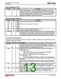
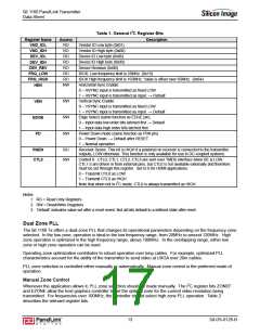
Table 1. General I2C Register Bits
Description
Register Name
VND_IDL
VND_IDH
DEV_IDL
DEV_IDH
DEV_REV
FRQ_LOW
FRQ_HIGH
HEN
Access
RO
Vendor ID Low byte (0x01)
RO
Vendor ID High byte (0x00)
RO
Device ID Low byte (0x06)
RO
Device ID High byte (0x00)
RO
Device Revision (0x00)
RO
IDCK. Low frequency limit is 25MHz. (0x19)
IDCK High frequency limit is 165MHz. Value is offset over 65MHz. (0x64)
Horizontal Sync Enable
RO
RW
0 – HSYNC input is transmitted as fixed LOW
1 – HSYNC input is transmitted as input. → Default
Vertical Sync Enable
RW
RW
RW
VEN
EDGE
PD
0 – VSYNC input is transmitted as fixed LOW
1 – VSYNC input is transmitted as input. → Default
Edge Select (same function as EDGE pin)
0 – Input data low order bits latched first → Default
1 – Input data high order bits latched first
Power Down mode (same function as PD# pin)
0 – Power Down. → Default after RESET
1 – Normal operation
RO
Receiver Sense. This bit is HIGH if a powered on receiver is connected to the transmitter
outputs, LOW otherwise. This function is only available for use in DC-coupled systems.
RSEN
CTL0
RW
Control 0. CTL0, CTL1, CTL2, CTL3 are sent over TMDS interface when DE is LOW.
CTL1-3 are driven in from external pins, but CTL0 is not available externally and therefore
must be set through this register. Set to 0 for HDMI applications.
0 – Transmit CTL0 as LOW
1 – Transmit CTL0 as HIGH
Note that when not in I2C mode, CTL0 is always transmitted as HIGH.
Notes:
1. RO = Read Only Registers
2. RW = Read/Write Registers
3. ‘Default’ indicates value set after a reset event. Not all bits default to a defined state after reset.
Dual Zone PLL
The SiI 1160 Tx offers a dual-zone PLL that changes its operational parameters depending on the frequency zone
selected. In the low zone, operation is ideal in the low frequency range, from 20MHz to around 120MHz. High
zone operation is optimized in the high frequency range, above 100MHz. In the overlapping range, either low
zone or high zone operation can be used.
Operating zone optimization contributes to robust operation over long cables. For example, optimized PLL
characteristics account for the ability of the transmitter to send video at UXGA over 20m cables.
PLL zone selection is controlled either manually or automatically. Manual zone control is the preferred mode of
operation.
Manual Zone Control
Whenever the application allows it, PLL zone selection should be made manually. The I2C register bits ZONEF
and EZONE allow the host graphics controller to set the optimal zone for the current video resolution being
transmitted. For frequencies over 100MHz, the controller should select high zone PLL operation. Table 2
describes the relevant register bits.
13
SiI-DS-0126-B

 SILICONIMAGE [ Silicon image ]